Resistor Specifications And How To Interpret Them
Consider the different performance characteristics that might be confusing
Resistors are one of the simplest electronic components. However, the specifications typically shown on datasheets can be confusing, and are often misinterpreted. In this article we discuss the different performance characteristics, the test conditions, and how to interpret the test results. We discuss potential differences in data presented by different manufacturers and what those differences will mean in terms of performance.
Resistor Power Ratings and Voltage Ratings
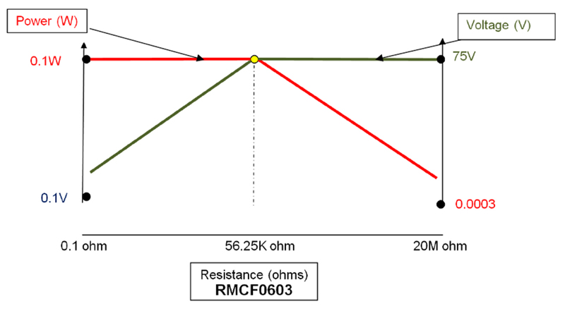
The power rating and voltage rating of a resistor are one common source of confusion. Simply put, the power rating is the amount of energy the resistor can dissipate in a given time at the designated ambient temperature.
Multiple voltage ratings are typically provided on a datasheet, but most often the primary concern is the maximum working voltage. Maximum working voltage is the maximum amount of voltage the resistor can withstand constantly without arcing. Maximum working voltage is often expressed as “Vrms.”
It is critical to adhere to both the power rating and the maximum working voltage rating to avoid reliability problems. For example, if a 10Ω 0603 chip resistor was subjected to the maximum working voltage of 75 volts, the resulting power through the part would be 562.5 watts. This far exceeds the power rating of the part.
Conversely, for high resistance values, the amount of electrical energy that the 0603 resistor can withstand is determined by the working voltage rating of 75 volts. If a 10MΩ 0603 was subjected to the maximum power of 0.1W, the voltage implied across the part would be 1000 volts, which surpasses the voltage handling of the part.
As shown in Fig. 1 above, it is clear that only at exactly 56.25K ohms can the 0603 resistor handle both 75 volts and 0.1W simultaneously. This value is known as the “critical resistance value”.
Click image to enlarge
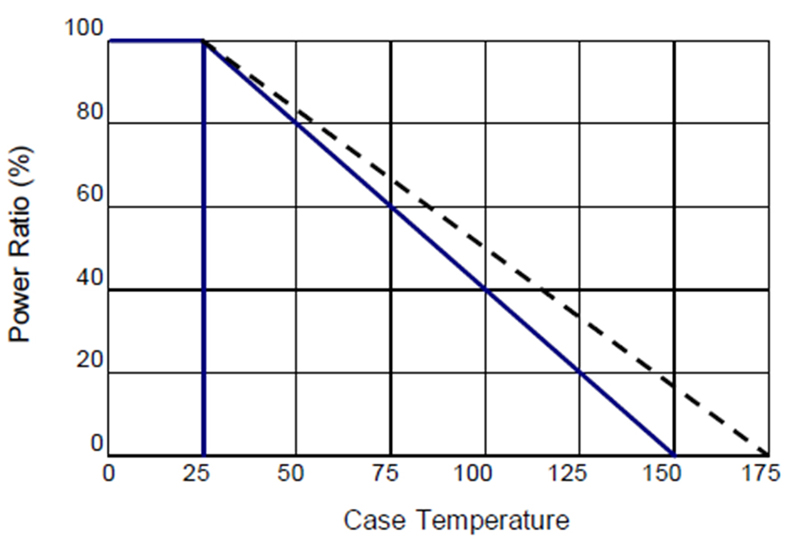
Figure 2. The derating curve
Another aspect of the power rating is the temperature at which heat dissipation is measured. Many resistors are rated at temperatures of at least 70ºC. This means the part can handle the designated power rating provided the ambient temperature around the part does not exceed 70ºC. However, there are some higher power resistors that are only rated for full power operation up to 25ºC. These power resistors typically require some type of external heat removal to operate at full rated power.
As can be seen from the derating curve in Fig. 2 above, if the part associated with this derating curve is to be used at 70ºC, the power rating must be reduced to roughly 65% of its full value. Operating this part at full power and elevated temperature will lead to excessive resistance shifts and potentially failure of the resistor.
Performance Characteristic Information
Performance characteristics provide information about how a resistor performs in a test or a set of tests. Engineers will regularly use this information to compare and contrast parts from different manufacturers. When resistor series are tested to a common standard such as AEC-Q200, it is relatively easy to compare performance.
When common test standards are not followed, both test conditions and the way in which test results are stated, can vary widely. These variations can lead to misleading performance statements. For example, nichrome based thin film resistors are susceptible to moisture corrosion. Some manufacturers will tout their nichrome elements as having superior moisture resistance, citing extremely low resistance shifts to biased humidity testing.
When examining those test conditions, the load or bias on the resistor is a critical factor. At full rated power, most resistors will generate enough heat that moisture will not condense on the part, making it appear robust in terms of moisture. But in many applications, precision nichrome thin film resistors will only see a fraction of the rated power. In these cases, the part will generate much less heat and the possibility of moisture condensing and collecting on the part increases. The resistance shift could be significantly different under a lower bias condition, such as 10% rated power. The test conditions is critical to understanding the results and ultimately resistor performance.
Click image to enlarge
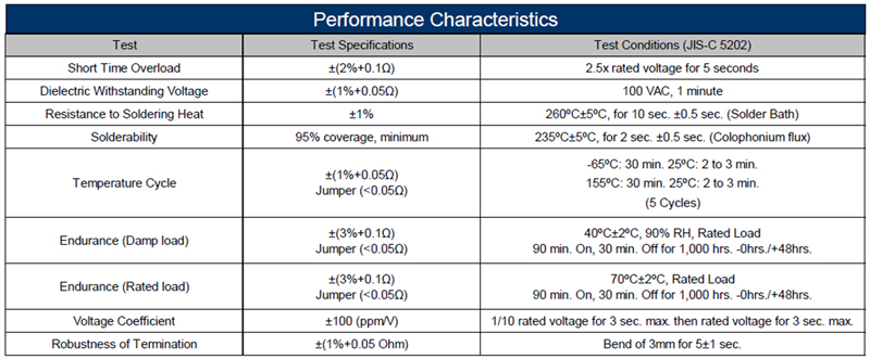
Figure 3. Example of performance characteristics
Another frequently asked question about performance characteristics is how to interpret the accumulated variation or tolerance stack-ups from the different potential sources of variation. Adding the maximum potential shift from all of the relevant tests provides the maximum expected resistance shift or worst-case scenario.
In practice, this is unnecessarily conservative for most applications and may result in the selection of a more expensive resistor with a tighter tolerance or lower TCR. It is important to remember that each performance characteristic test is independent. Some of these tests will typically have a positive shift in resistance and some will typically have a negative shift in resistance. In addition, the typical test performance will differ from one resistor technology to the next. In most cases, the actual resistance shift experienced in the circuit or application is a fraction of the sum of the individual test tolerances. It is advisable to contact the factory about specific stability requirements over the life of a given circuit or application for a particular resistor or series of resistors.
It is also important to understand if the change in resistance shown in the performance characteristics is typical performance, or absolute maximum limits. Some manufacturers will show typical results and not state it explicitly unless they are asked specifically by the customer. Typical results are usually 2 to 3 times better than the actual test specification. This creates the false impression that their part is superior to other similar products when the actual performance is no better and in some cases inferior.
Summary
Effective electronic designs can be achieved when critical specifications are taken into account. When selecting resistors, the design must not violate the power rating or the voltage rating of a given device; these are resistance dependent parameters. Power ratings must be reconciled with the appropriate operating temperature. If the circuit operates at temperatures above the rated temperature of the resistor, then the power handling of the resistor must be derated appropriately.
Performance characteristic testing must be closely examined to determine what tests are relevant to the application. Test specifications must be reviewed to ensure the test conditions are the same, and test results must be properly interpreted. Test results must be verified as actual maximum possible shifts or typical performance to ensure a balanced comparison. Only then should a decision by made on the actual performance of each resistor.
Finally, when considering tolerance stackups, the accumulated variance or worst-case scenario does not consider the distribution of the individual, independent variables. This can lead to an unnecessarily constraining design and would make typical commodity resistors impractical to use. Whenever there is a question about whether a resistor is suitable for a particular design, it is recommended to have factory engineers examine the design in detail to ensure the correct product is chosen.
More information and data sheets available at: www.seielect.com


