Author:
Dirk Geiger, Infineon Technologies
Date
02/01/2024
 PDF
PDF
Click image to enlarge
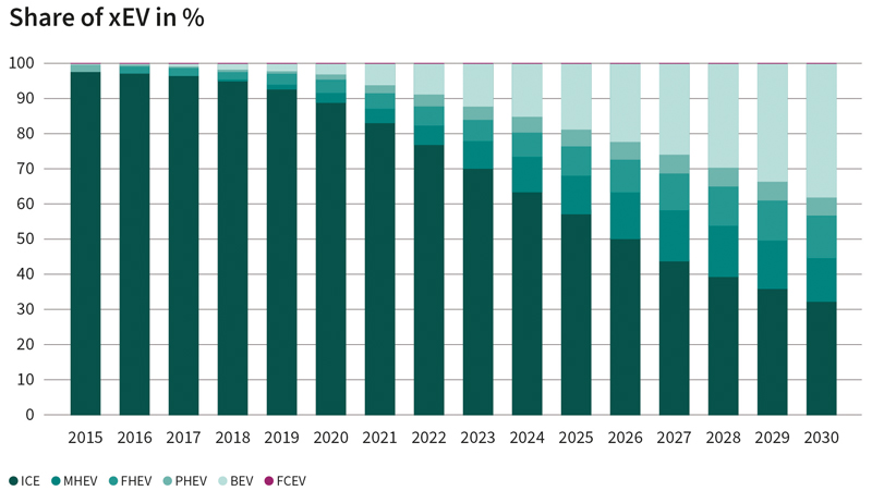
Figure 1. Share of xEV in percentage
The high-voltage energy stored in the EV battery is converted by HV-LV DCDC conversion systems into a low voltage that can be used by the vehicle's electrical and electronic systems. This conversion is critical to the intended operation of the vehicle as it contributes to maintaining the power supply to vital systems such as electric motors, lighting, and navigation systems. As such, it is essential that the system is built to meet the functional safety standards set by the automotive industry to protect both the vehicle occupants and the vehicle itself.
Typical grids and power conversions in an electric vehicle include both HV (high voltage) and LV (low voltage) requirements.
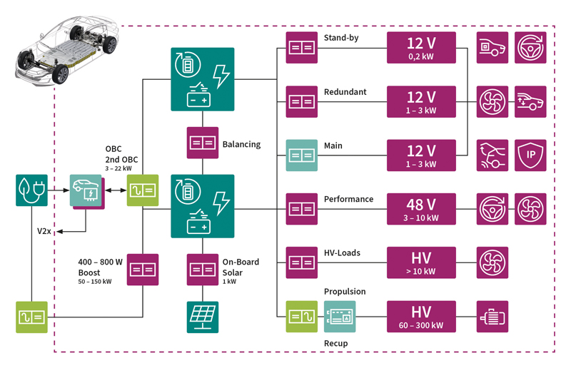
With increasing electrification and the rapidly growing availability of ADAS, the complexity of the network will increase significantly in the coming vehicle generations (Fig. 2). To keep up with the increasing requirements on the overall system, such as redundancy, independent or diversified energy sources, the main battery could be divided in two, so that the charging and the load sides can be separated. For example, a setup with two 400 V batteries would allow charging at 400 V or 800 V, depending on whether the batteries are connected in series or in parallel. Similarly, a traction inverter can operate at 400 V or 800 V on the load side, giving the designer more options while focusing on cost or efficiency.
Click image to enlarge
Figure 2. The increasingly complex and demanding energy conversion in future drivetrains can be realized with chipsets from Infineon
Although it sounds simple, such a setup also brings additional challenges, like the need for a more complex battery management system and the management of switches for a dynamic battery string configuration. But there are other issues to consider when optimizing the power conversion system, too:
· Multiple HV-to-12-V DCDC converters are needed to supply additional loads, such as heat pumps or self-regulating heaters.
· A standby HV-to-12-V DCDC converter, typically 100 W to 300 W, is necessary to charge the 12 V battery during parking or to provide power capacity for large SOTA updates.
· An HV-to-48-V DCDC may be required for even more powerful loads, such as a heater for plug-in hybrid electric vehicle exhaust air cleaning that meets new Euro VII emissions standard.
· To balance both batteries, a special DC-to-DC system could be implemented.
· Some vehicles offer a solar upgrade, where solar cells are added to the roof to boost range.
Overall, the additional flexibility in the design of the electric drivetrain enables scalable platform solutions and easier adaptation to the existing charging infrastructure.
To take advantage of such a drivetrain, separating the on-board charger (OBC) from the DCDC converter is becoming more attractive. OEMs are starting to introduce dedicated DCDC units that integrate the different application requirements while separating the OBC. This allows the industry to focus on standardized and optimized OBC solutions with integrated communication at the application level that meet the ISO15118 standard. The separate DCDC unit would thus be optimized for specific vehicle requirements.
But ultimately, this is not just about additional flexibility in the drivetrain, but also about additional functions and values. For example, a limp-home function can easily be implemented with two 400V batteries. If one battery pack fails, it is switched off. With the other, however, the vehicle can continue to be operated reliably and thus safely reach the desired destination.
A typical DCDC conversion system
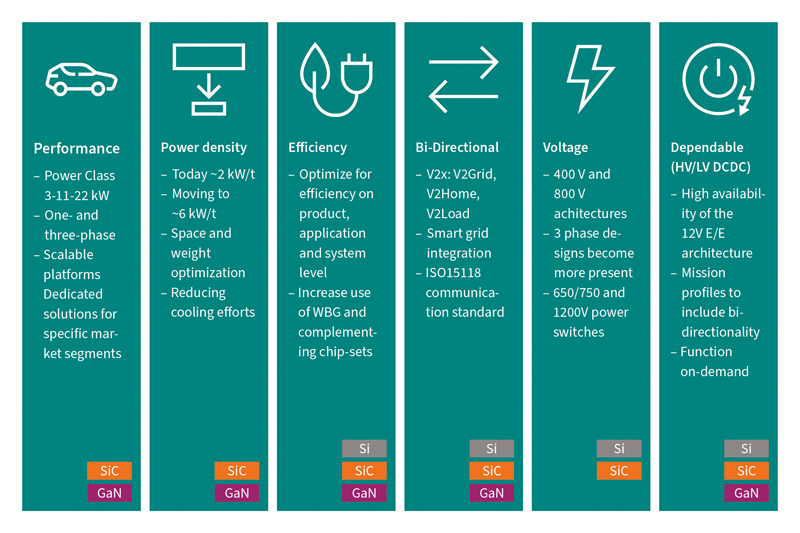
A typical SiC-based HV-LV-DCDC conversion system (Fig. 3) for electric vehicles consists of many different components: SiC Power MOSFETs, Si-Superjunction MOSFETs or IGBTs for switching, Si Power MOSFETs for synchronous rectifying, magnetic components and capacitors for energy transfer and filtering, control circuits for voltage regulation and protection, heat sinks for cooling and thermal management, PCB and packaging for integration and protection of components, as well as safety and protection circuits for under-voltage, over-voltage, over-temperature, and over-current conditions.
Click image to enalrge
Figure 3. Leading trends for HV-DCDC power conversion applications
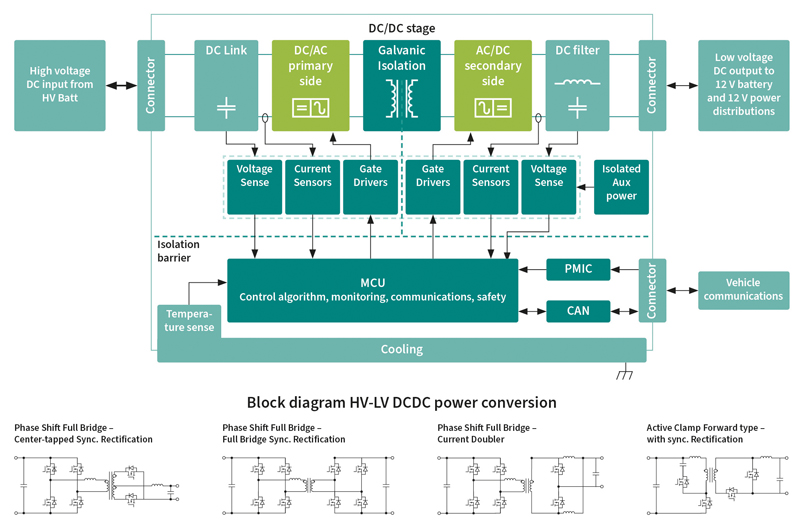
For a high-voltage to low-voltage DCDC converter (Fig. 4) for electric vehicles, it can be difficult to determine the exact relationship between semiconductor cost and total application cost. This is because it depends on several factors, such as the complexity of the converter, the size of the system, the quality and quantity of components used, and other design considerations.
Click image to enlarge
Figure 4. Function block and topologies of a HV DCDC/OBC
However, developing an HV DCDC is not just about semiconductors. With growing production volumes, new platform concepts, and flexible vehicle configurations, engineers must also consider manufacturability, repairability, sustainability and recyclability. Infineon's complete and complementary chipsets for HV-DCDC applications come in handy here, as they have been designed with such applications in mind. Developers thus have a semiconductor one-stop store at their disposal, offering them all the components they need and allowing them to focus entirely on application capabilities. This enables them to bring their differentiated, powerful, and efficient application solution to market as quickly as possible.
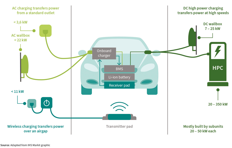
But developers must also consider the integration of the electric vehicle into the overall charging infrastructure and the power grid. And other questions must not be ignored either: Is enough green electricity being produced and is it available? Will the electric vehicle be charged with alternating current or with fast direct current? How can the electric vehicle be part of the power grid in a V2X scenario? Might the vehicle even be a mobile energy bank, storing valuable energy that can be fed into the grid when needed? All these considerations can change the usage profiles of vehicles and applications. However, they also enable new use cases and business models. Depending on the application, different components are needed for implementation: A vehicle that is charged via a DC wall box requires different components than a vehicle designed for AC charging stations (Fig. 5). This makes it even more important for a developer to have a supplier with a broad portfolio that considers many different industries and application scenarios.
Click image to enlarge
Figure 5. There are different approaches for the implementation for EV charging solutions. Infineon offers solutions for all of them from a single source
Future challenges
Looking ahead, these developments open the door for the next generation of vehicles and applications (Fig 6.). Soon, for example, efficiency optimized OBCs could be air-cooled which allows for more flexibility in vehicle integration and reduces the cost for liquid cooling. The use of 400 V batteries could even eliminate some DCDC applications entirely, including a DCDC boost from 400 V to 800 V.
Click image to enlarge
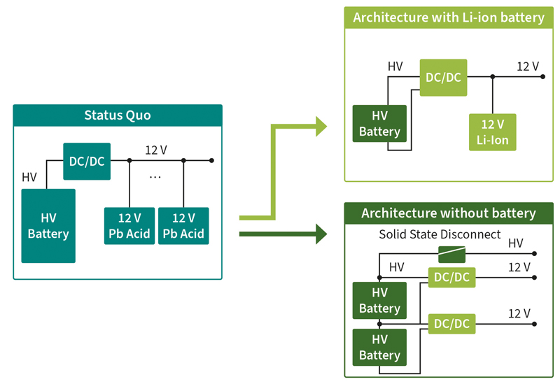
Figure 6.Further development of drivetrain architectures
With HV-to-12-V DCDC, even a 12-V supply is possible. This raises the question of whether a special 12 V battery will be necessary at all in the future. An important point, because the 12 V battery used today is generally a lead-acid battery. Although the use of lead is currently still covered by an exemption in the RoHS and ELV (End of Life Policy) guidelines for vehicles, these must be reviewed every few years. So, the exemption might expire sooner or later. By then at the latest, the lead-acid battery would have to be replaced with a Li-ion battery, which would lead to additional costs. For this reason, there are considerations to simply remove the 12 V battery altogether. However, this requires a completely new drivetrain and network concept. Think, for example, of critical functions such as the brake-by-wire or steer-by-wire application. Their operation must not be compromised under any circumstances. Redundancy is therefore urgently required, from the power source to the load, including the two main batteries, redundant HV-12V DCDC, HV load path. This allows the drivetrain to operate reliably without a 12V battery and continue to enable ADAS and by-wire functions. At the same time, weight and space requirements are reduced, which in turn improves vehicle efficiency. In addition, scalable vehicle platforms can be realized that address both affordable market segments and high-performance vehicles.
New battery concepts
Now that we have looked at vehicles with two batteries and potential added value, why not think a little further? How about dividing the main battery into even smaller segments, such as multiple 12 V modules? On the load side, the high voltage would be generated by connecting the battery modules in series in 12 V increments upward. This approach would eliminate the need for special DCDC converters since the desired voltage would be provided directly by the battery itself. However, this would require intelligent battery management to ensure that all modules are charged and discharged evenly.
In addition, the battery could generate not only direct current but also alternating current via fast semiconductor switches, for example to operate the traction motor directly. With this setup, a dedicated inverter can be eliminated. With a charge that can be easily adapted to the existing charging voltage, an ACDC converter would also be unnecessary. In such a multi-string battery, redundancy is already included, and scalability is readily available.