Much-improved 1W isolated DC/DC converter
With their ability to drastically simplify provision of low-power isolated power rails that are commonly required in applications such as process control and industrial communications interfaces, encapsulated though-hole DC/DC converters became immensely popular following their introduction more than two decades ago. The available range of input and output voltages has rapidly evolved to reflect the commonest industrial levels, leaving the migration to surface-mount packages as the most noticeable change to the original product's concept. Now, new developments are taking SMT packaging to an even higher level. Designing a tiny DC/DC converter that meets contemporary performance expectations and that provides a degree of future-proofing is not straightforward. The first challenge is to select a topology that meets the size constraints that miniaturisation demands, yet is capable of adequate output power delivery, isolation and regulation. The chosen approach should be able to address a range of common input and output voltages as well as ideally being extensible to deliver more power from a similar platform. The need for an isolation barrier that withstands typically 1 kVDC implies transformer coupling that requires ac primary drive and secondary rectification whose implementation inevitably involves compromises that mainly lie between component count and conversion efficiency. The conventional minimum component count approach uses a saturating �Royer' circuit, a self-oscillating push-pull topology, in which a pair of bipolar transistors drive antiphase primary transformer windings and derive their base currents from opposite ends of a centre-tapped auxiliary winding. Applying a dc input voltage through a start-up bias circuit turns on one transistor, which remains on until the transformer's core saturates, the transistor gain-limits and all transformer winding voltages collapse. Residual energy in the transformer causes reversal of the polarity of winding voltages which switches off the first transistor and biases the second to the �on' condition which then starts to drive its winding to saturation. The process repeats to sustain oscillation at a frequency that is proportional to the input voltage, creating a square-wave output voltage for rectification. This basic circuit has several limitations, notably its lack of active regulation—the output voltage is a function of the input voltage, internal losses and the transformer's turns ratio—together with poor efficiency due to semiconductor switching and core magnetic losses at the high frequencies that miniature transformers require. Well-known variations around the theme include modifying the circuit to avoid lossy core saturation by using a second drive transformer which has potentially higher efficiency but at the cost of complexity and size.
Electrical specification enhancements By combining proprietary circuit enhancements and recent component fabrication techniques, designers can improve the load regulation of such a converter. For example, Murata Power Solutions' engineers were able to increase their MTU1 part's load regulation performance to a maximum -4, +5.5% from 10% of full load upwards. By comparison, previous ranges achieved -7.5, +10% see figure 1. For many applications, the load regulation these enhancements offer obviates the need for inefficient and space-hungry linear post-regulation stages. At the same time, a major improvement to the part's toroidal magnetics helps to improve efficiency to the range of 83 - 88%. Also, the switching frequency has reduced from nominally 110 kHz to 82 kHz for 5V-input MTU1 parts and 90 kHz for its 12V-input variants. These steps likewise contribute towards lower dynamic losses. Notably—and as figure 2 shows—the efficiency curves reach or exceed 80% at around 40% of output power capability and are virtually flat from 50% upwards. These efficiency improvements translate into an approximately 56% reduction in internal power dissipation that reduces internal hot-spots maximising reliability while minimising the heat load that the host equipment has to accommodate. The MTU1 series requires no derating over its -40 to +85°C operating range. Other electrical specification enhancements include reduction to reflected ripple current from around 30 mA peak-to-peak to 5 - 6 mA and isolation capacitance reduction of between two and three times. These attributes greatly ease input filtering needs. The reduced capacitance further isolates input and output, making the part far less susceptible to transmitting noise through its isolation barrier which could potentially disturb sensitive loads.
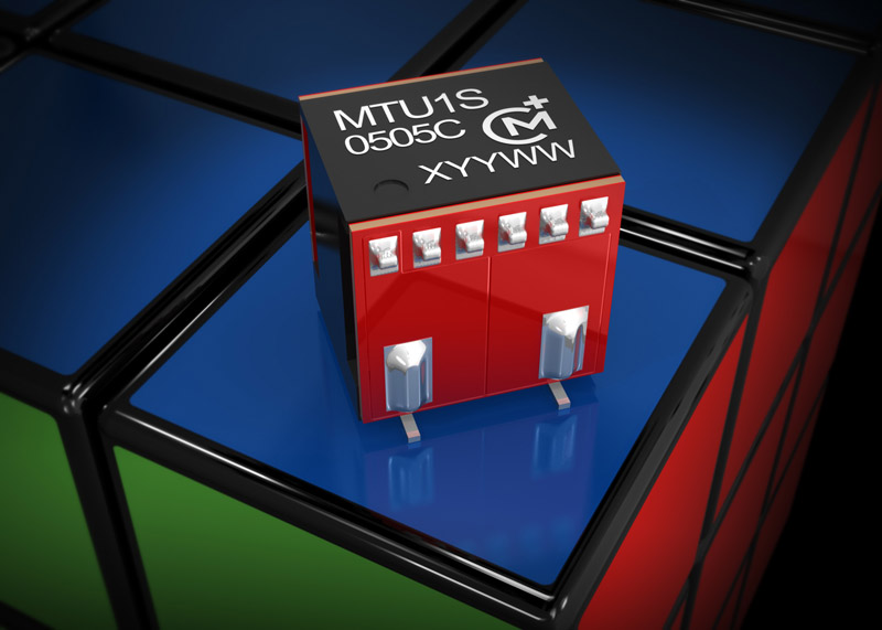
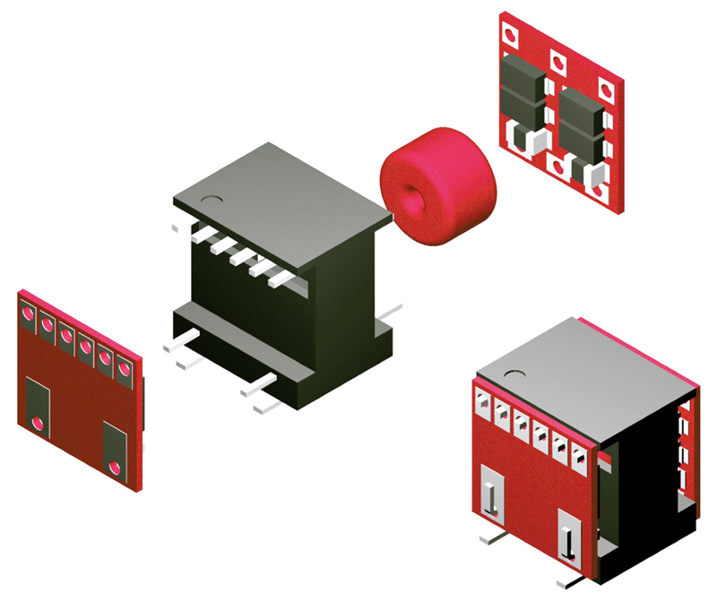
Footprint shrinks But the most dramatic improvement that the MTU1 series introduces is the part's new footprint, which shrinks the 12.70 x 11.70 mm pad land pattern that industry-standard parts use to just 9.10 x 6.08 mm. This represents a footprint area over the new device's pins of 0.69 cm2 and an effective power density of 1.71 W/cm3 for a cube-like outline that measures 8.2 x 8.4 x 8.5 mm. As figure 3 shows, the MTU1's RoHS-compliant housing conceals a patent-pending open-frame construction beneath its UL 94V-0 specification packaging material.
Design for manufacture achieves MSL1 Significantly—and unlike some plastic-encapsulated packages that industry-standard components employ—the MTU1's composite assembly has a level 1 rating for moisture sensitivity (MSL1). Moisture absorption and retention is a major issue for many surface-mount devices as it can generate large stresses when the part is subjected to a rapid and very large temperature rise, such as during lead-free reflow processing that can reach peak temperatures as high as 245°C. The resulting outgassing can easily destroy the device and is generically known as "popcorn cracking". As a result, component manufacturers classify the moisture sensitivity of their parts on a scale that IPC/JEDEC J-STD-20 rates from 1 through 6, where an MSL1 rating signifies that the part is immune to popcorn cracking regardless of its exposure to moisture. The MTU1's package design dispenses with the pre-baking procedures that many parts rated less than MSL1 routinely require and that can negatively impact upon their solderability. Additionally, for MSL1 rating, no expensive handling and storage precautions are necessary. Furthermore, the MTU1's open-frame construction is designed to reflow safely during processing and negate any tendency towards internal solder bridging, while the cube shape's flat top surface makes it easy for standard vacuum pick-&-place nozzles to manipulate. www.murata-ps.com


