For off-grid and mobility applications
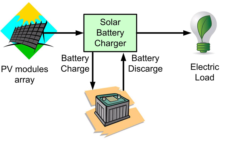
Figure 1: Typical off-grid PV system
Photovoltaic cell technology over the last few years has reached levels of cost and efficiency that enable its use in new markets. Due to the varying sunlight conditions, energy storage in batteries is essential. Also, the need to extract the maximum amount of energy possible from a PV system has led to the development of increasingly efficient maximum power point tracking devices.? The increasing interest in environmental issues due to the production of electric energy from fossil fuels and their growing cost are drawing remarkable amounts of capital and interest of the scientific community to energy production techniques from renewable sources.??Distributed energy production allows rural areas to be supplied where grid connections are impossible, or too expensive. The cost of PV modules is dropping significantly thanks to the development of emerging silicon technology and the increasing competition between module manufactures. For these reasons the PV market is expected to grow even faster in the coming years. Off-grid installations are a niche market today due to the fact that in developed countries electric grid is sufficiently widespread and reliable for small producers. Nevertheless off-grid PV is going to become a large market with the diffusion of PV installations in rural areas of developing countries. ??An off-grid PV system, also called a stand-alone system is designed to provide electricity to homes or remote loads, without drawing supplemental power from the electrical utility. This system consists of a PV panel or array of panels, battery charger and a battery bank. In order to understand the main requirements of an off-grid PV system optimised for mobility applications, it is necessary to review the simplified electric model of a PV cell, and the techniques used to extract the maximum available power from a photovoltaic source.
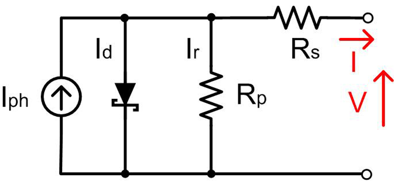
PV cell model and PV module A PV cell can be modeled by a current generator in parallel with a diode (Figure 2). The photo current (Iph) is a function of the solar irradiation. A series resistor Rs and a parallel resistor represent respectively the voltage loss and the leakage current of the cell. The diode D characterises the non linear behavior of the cell and the dependency of its performance on ambient temperature.
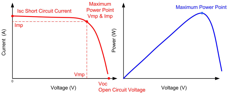
The typical voltage to current (V-I) and voltage to power (V-P) characteristic of a PV cell is shown in figure 3. The open circuit voltage (Voc) is about 0.6V for a crystalline solar cell and it is relatively independent of the solar irradiation. The current produced by the cell depends on the irradiation, ambient temperature, surface area of the cell, and the voltage at which it is operating. The maximum power point (MPP) is the point at which the solar cell current (Imp) and voltage (Vmp), produces the maximum power. At MPP of the curve, the voltage is about 80% of the Voc. A PV module is realised by a series of cells called strings. Each string is protected by a bypass diode that prevents damage through overheating if one or more cells are shaded or defective. These strings are connected in series or parallel to get respectively higher voltage or higher current out of the panel. In ideal conditions, with uniform irradiation and temperature among the panels, the V-I and V-P characteristics of a module are similar to that of a cell, except for their different scale factor. Several factors influence the output performance of a photovoltaic module: cell material, sunlight intensity, cell temperature, load resistance and irradiation mismatch. Because all cells of a module are connected in series, they all share the same current. The cell that has lower irradiation will impose the current on all the other cells.?For this reason even partial shading of a photovoltaic module will result in a dramatic reduction in output. ??The actual impact of energy yields due to partial shading mismatch is difficult to predict with a simple calculation because it depends upon many factors such us internal module cell interconnections, module orientation, PV module array series-parallel connections and the specification of the solar battery charger. PV Controller Types PV off-grid systems require specific solar battery chargers connected between the PV panels and the battery (figure 1).??The primary function of a charge controller in an off-grid PV system is to maintain the battery at high state of charge (SOC) while protecting it from overcharging, which can lead to the electrolyte boiling. Various types of charge controller are available. These include simple switch on/off controllers, pulse-width modulated (PWM) charge controllers which charge the battery with constant voltage or constant current (the most commonly used controllers in PV systems), and maximum power point tracking (MPPT) controllers. The MPPT types are more costly and better suited to large systems where the investment in an expensive MPPT regulator gives quick returns. ?The actual benefits of MPPT depend on the operating temperature of the PV module, the battery state of charge, and possible mismatch shading present on the PV array. ??MPPT solar charger controller An MPPT controller is a high efficiency DC-DC converter which performs as optimal electrical load for the photovoltaic panel or array, and converts to a voltage and current level that is more suitable to charge the battery.??The controller allows tracking the maximum power point of the array throughout the day in order to deliver the maximum available solar energy to the battery. ??Step-down MPPT controllers allow a higher voltage array to be connected to a battery bank, with some saving on wiring sizing. However it presents the same limitation of a standard PWM controller when PV operating voltage falls below the battery voltage (due to temperature or partial shading).?This limitation can be problematic in small off-grid systems like PV streetlights and mobility applications.?
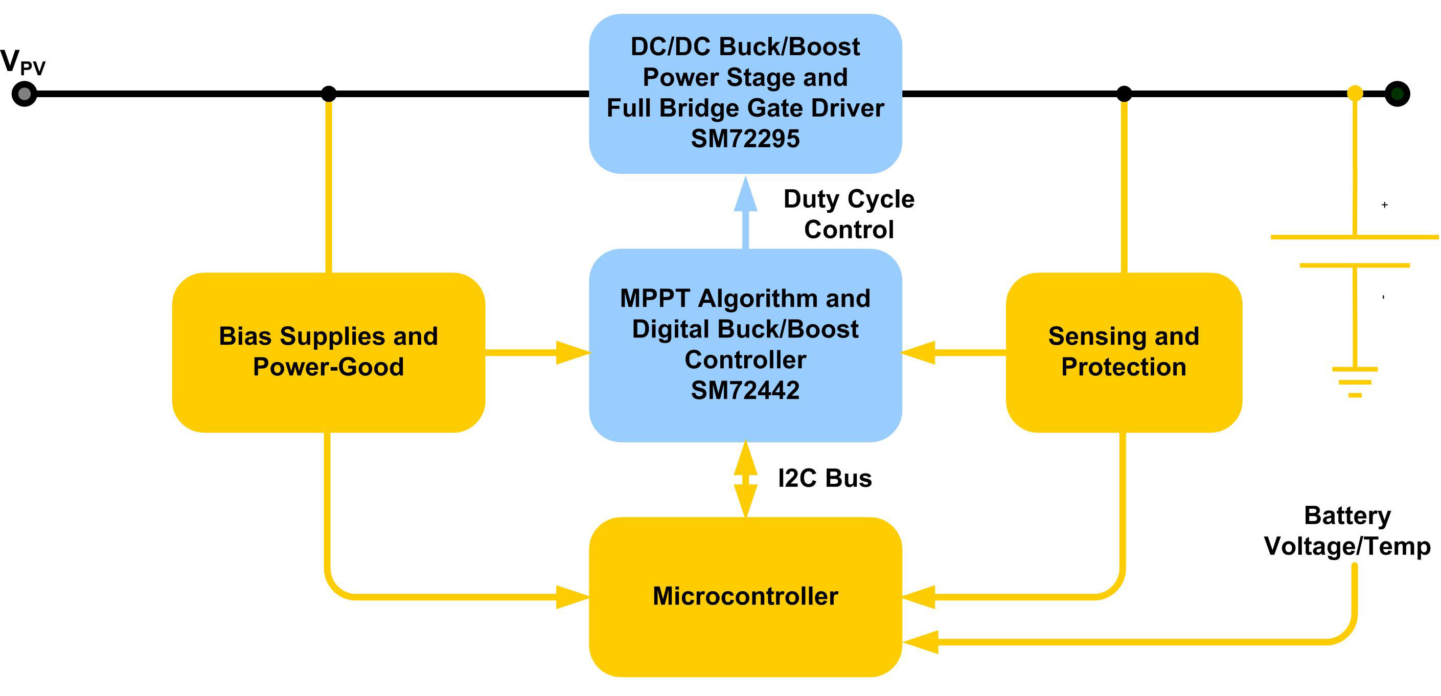
Renewable Energy systems for mobility applications:?Off-grid systems for mobility applications like RV, boats and vehicles share the same basic components of a standard remote energy system for home-rural installations. The primary difference is that the solar panel array is smaller than that of a typical off-grid home installation, and the PV modules needs to be adapted to relative small areas with different characteristics. In a typical off grid renewable energy system, much care can be taken to avoid shade from the surrounding obstacles. In RV or any mobility system, shade can not be avoided or planned by definition. Different tilts, orientation, partially shaded areas, salty environments, dirt are all synonymous of mismatch between modules or group of cells. Amorphous or thin film solar electric panels work much better under these partial shading conditions. The downside with these panels is that they are larger in overall area for the same given wattage of a traditional poly-crystalline or mono-crystalline solar panel. ?Figure 4 shows the block diagram of a DC-DC MPPT battery charger designed with SolarMagic™ chipset from Texas Instruments. The SM72442 mix signal device implements a proprietary MPPT algorithm that reacts to irradiation changes in a few msec. It's high integration level and low power consumption allows the design of high efficiency MPPT controllers. Use MPPT DC-DC controllers with a wide input voltage range, in order to adapt to different PV array configurations and shading conditions. Avoid configuration with long strings of cells to minimise the partial shading effect, and ensure a DC bus voltage adequate to charge the battery in partial shading conditions. Distribute MPPT controllers when possible: distributing more DC-DC controllers with MPPT among modules or arrays addresses the problem of partial shading and mismatch conditions. A standard battery charger controller or MPPT with only step down function would not be able to reach the MPPT point and deliver to the battery only one third of the available power. An MPPT charger with buck-boost configuration and wide input voltage range will recoup the maximum energy available. Conclusions Through careful design of the PV installation and the use of distributed MPPT battery chargers, it is possible to achieve highly efficient off-grid energy systems, contributing significantly to a reduction in the dependence on fossil fuels and consequently reducing emissions. www.ti.com ?


