The goal for the battery management system is to allow all battery cells to be safely charged to the highest possible capacity
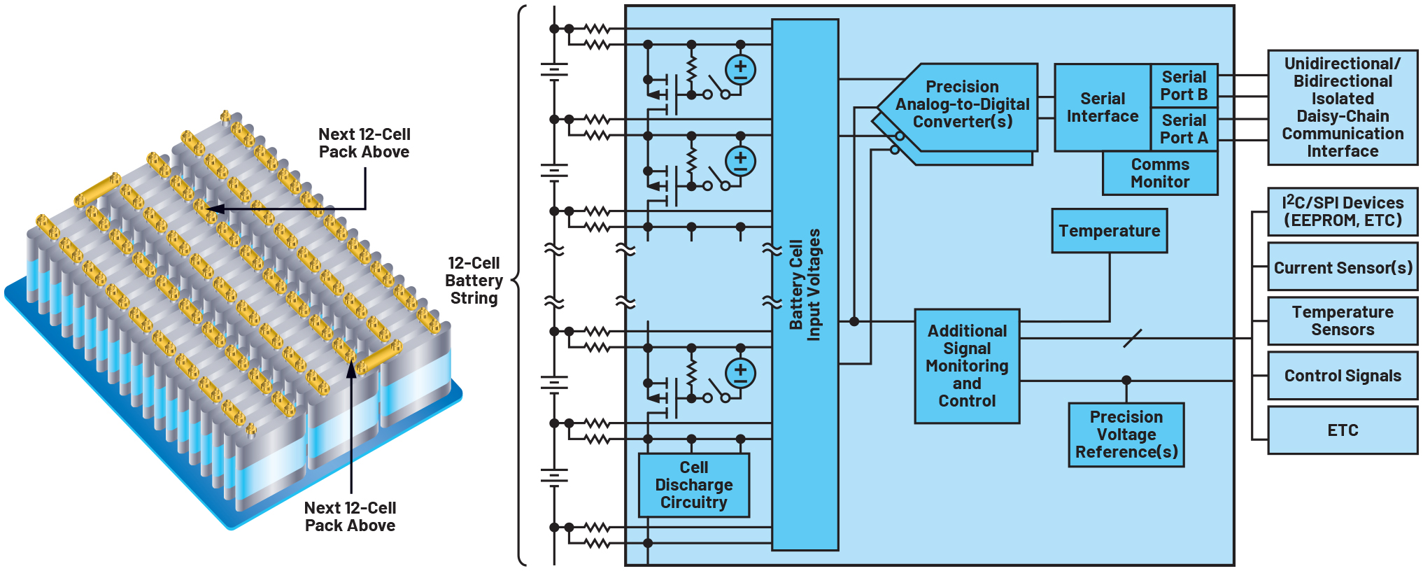
Figure 1. Simplified description of the multicell battery monitor
For decades, the automotive industry has slowly consolidated, while technology and brand differentiation has decreased. The powertrain, the system that transfers energy into motion, is arguably the auto manufacturer’s most prized intellectual property, with more than a century of refinements behind it. In this context, the emergence of entirely new automotive companies is nothing less than remarkable since the powertrain technology is the one that is being challenged.
A typical internal combustion engine (ICE)vehiclehasa15-gallonfueltank,whichis equivalent to nearly 500 kWhr of electrical energy. 15 gallons of gasoline translates to a range of 375 miles in an ICE; 500 kWhr of electrical energy translates to a range of 1450 miles in an EV. This enormous efficiency advantage is why EVs will eventually triumph, but the last leg of this journey is yet to be mapped out. The biggest problem facing today’s generation of EVs is that they cannot carry enough battery capacity to match the range of an ICE vehicle.
What is the challenge?
The battery pack of an EV consists of hundreds of individual battery cells, operating in series to create voltages from 400V to 800V. Overcharging and over discharging can damage or prematurely age a cell, which can reduce capacity or lifetime, and eventually cause cell failure. The primary function of the BMS is to determine and control the SOC and SOH for every cell in the long series that make up a pack. Charging any Li-Ion cell to 100% of its SOC or discharging to 0% SOC will degrade its capacity. Determining SOC requires measuring cell voltage and temperature, and the accuracy of these measurements directly determines how well SOC can be managed. In sum, the BMS electronics are the lynch pin for maximizing operating range, lifetime, reliability, and safety of an EV’s battery system.
It is no simple feat to accurately and continuously measure all battery cells connected in a long, high voltage string in a tightly coordinated way. Measurements need to be immune from the corruption of high electrical noise created by inverters, actuators, switches, relays, etc. The electronics themselves need to be electrically isolated due to the high voltages of the pack. And finally, the electronics need to operate for years through wear and tear, weather, and the age and mileage of a vehicle.
At the heart of the BMS
As a leading provider of integrated circuits (ICs) and solutions, ADI’s battery management products focus on a few key areas: individual cell measurements (cell monitors), overall pack measurements (pack monitors), communication networks to interconnect devices (via wires or via a wireless network), and software to control these devices. The goal for these electronics is to allow all battery cells to be safely charged to the highest possible capacity, ensuring that the complete pack obtains the largest storable energy to maximize the vehicle range.
Arguably, the most critical device is the high voltage cell monitor IC. Cell monitor ICs measure the cell voltages and temperatures of series-connected battery cells, typically 12 cells per monitor. Cell voltage and temperature are the key parameters; measurement accuracy and synchronicity are the key characteristics.
Combined, this information enables the BMS to operate the cells at the full extent of their safe operating range without stressing them. So, the performance of these cell monitors is critical for a BMS to maximize a vehicle’s range, cost, weight, and reliability. Since measurement error translates to less effective battery management, ADI’s BMS products have always offered the industry’s most accurate measurement capability.
ADI’s recent introduction of the ADBMS6815 family of precision cell monitors offers an ideal combination of features to achieve safety, performance, and cost-effectiveness. This family consists of three basic devices, differentiated by the number of cells that each monitor: The ADBMS6816 monitors six battery cells, the ADBMS6817 monitors eight battery cells in series, and the ADBMS6815 monitors 12 battery cells in series. The three different cell monitor counts can address different cell configurations for a wide range of battery pack configurations.
Furthermore, these parts can be combined in a mix and match fashion to createan ideal quantity of cell monitor channels. Because the operating environmentincludes extreme electrical noise, they also include adjustable low-pass filtering that reduces this noise, ensuring high fidelity measurements.
Click image to enlarge
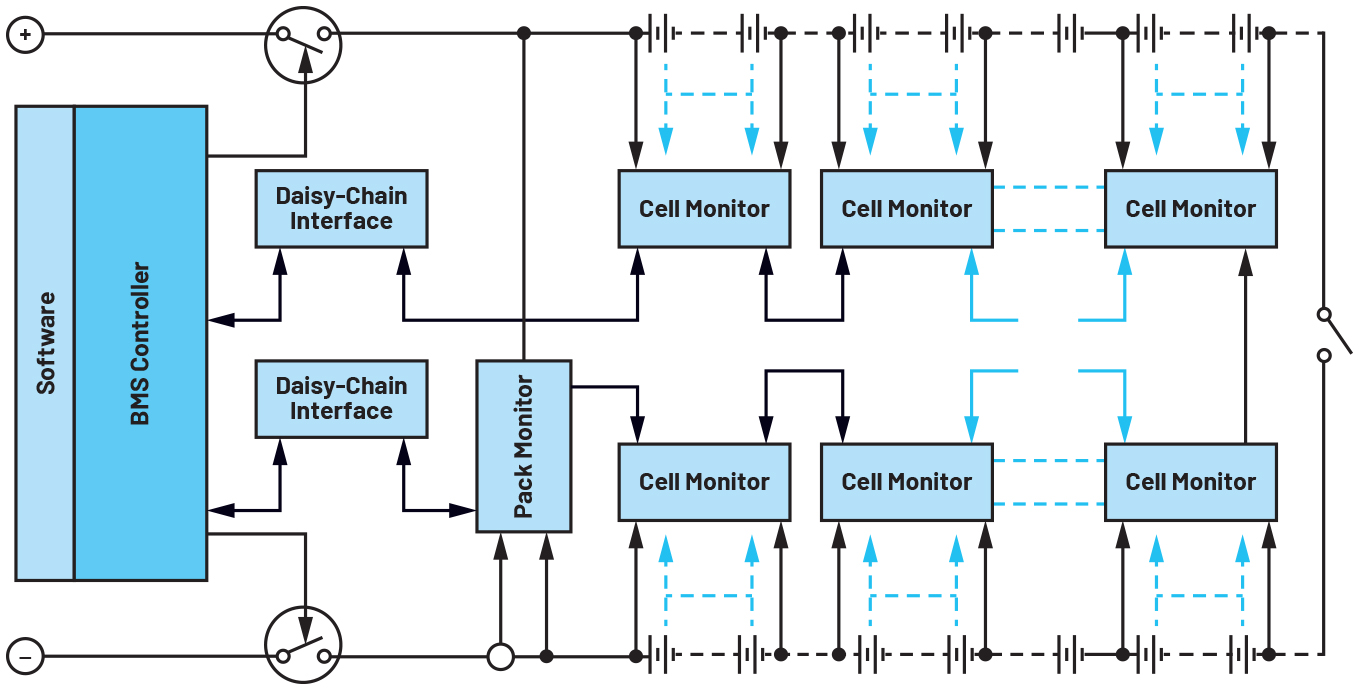
Figure 2. Outline of a wired BMS
ADI BMS communication technology
The ADBMS6815 family of cell monitors are designed for daisy-chain interconnection using a 2-wire communication interface called isoSPI. This is a robust, EMI-insensitive, and electrically isolated network that allows ADI’s BMS devices to be operated, polled, and controlled synchronously from the BMS microcontroller. This enables all cells in the pack to be measured synchronously with pack current and pack voltage using an ADI pack monitor device. This daisy chain can be operated with one path to each device, or with dual paths in a loop configuration. The loop allows for access to all of the cell monitor data in the event that a wire or connector fails.
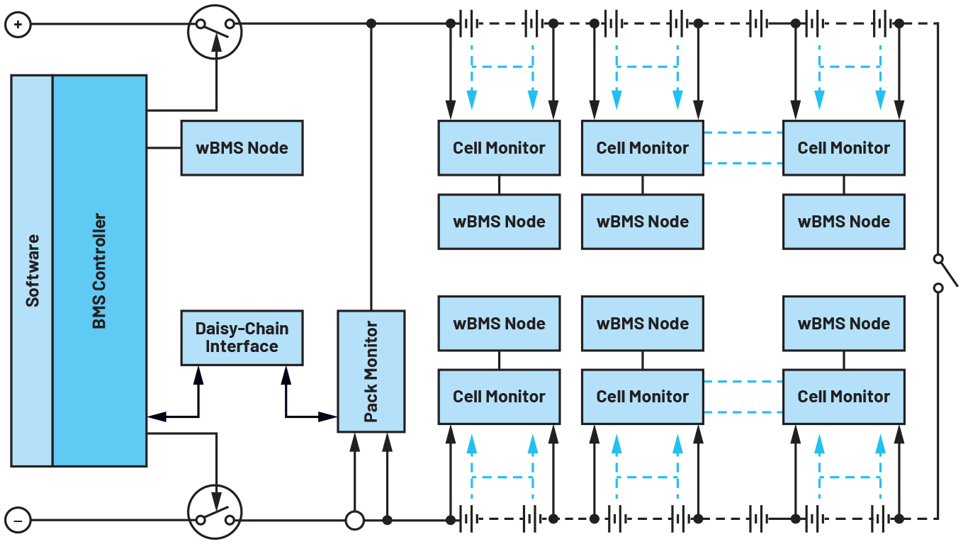
The ADBMS6815 family also supports operation in a wireless BMS (wBMS), where the wired daisy chain is replaced with a 2.4 GHz wireless BMS node at the cell monitors.
Click image to enlarge
Figure 3. A wBMS replaces the comms wires with a radio
Safety
Among all the goals of a BMS, ensuring that the battery pack is safe is the mostimportant. Recognizing and remedying potential failures within an IC requires built-in self-test capability and redundancy. These functions include redundant measurement paths, improved synchronization between input signals, self-test capability, and many more.
The ADBMS6815 family of parts has been designed to support the ISO 26262ASIL-D standard.
ISO 26262 is a universally adopted automotive functional safety standard, designed to ensure safety throughout the lifecycle of automotive electrical equipment and systems. ASIL-D is a risk classification within this ISO standard that represents the highest level of automotive safety in a system. ADI’s components are designed and certified to support ASIL-D to ensure that automotive manufacturers using ADI’s components can achieve this critical milestone.
Furthermore, by meeting the ISO26262 standard, designers can generally address other functional safety standards such as IEC 61508 to meet the standards for non-automotive applications, as well.
Low power cell monitoring
In addition to ensuring a stable, predictable, and reliable source of energy to power the vehicle, the BMS must ensure that the cells themselves are always safe. While it is a rare occurrence, a battery cell defect can cause a cell to short overtime and lead to thermal runaway with catastrophic results. For this reason, the BMS monitors for conditions that could indicate any potential problem.
Battery cells are not inert just because they are not in use. As electrochemical devices, they change overtime even when at rest. In other words, the progression of a failing cell can continue even while a vehicle is not operated. To provide continuous monitoring of the cells within a battery pack, even while a vehicle is in a key-off state, ADI has developed low power cell monitoring (LPCM). LPCM is an advanced cell monitoring feature that periodically and autonomously checks key parameters of the battery cells. With the LPCM feature, the cell monitors alert the BMS to wake up and run appropriate checks if they detect any potential concerns. The BMS is also alerted if the cell monitors fail to provide a periodic positive confirmation.
Flexibility, capability,and cost-effectiveness
The ADBMS6815 family offers an ideal combination of features to address a broad range of requirements, complementing the safety, reliability, and performance already outlined. These devices use the same package and pinout, allowing designers to combine the different channel counts (6, 8, 12 battery cells monitored with each device) to create a general design that can be populated to address abroader range of battery pack or cell module configurations. These parts also include general-purpose I/O that can operate as digital inputs, digital outputs, or as analog inputs. When operated as analog inputs, they can measure any voltage up to 5V with the same measurement accuracy as the primary cell measurements. Furthermore, these auxiliary measurements, such as temperature or current, can be synchronized with individual cell measurements for more accurate SOC calculation. These I/O pins can also control I2C or SPI subnode devices, enabling more complex functions, such as the addition of multiplexers for expanded analog inputs or EEPROM to store calibration information. Finally, these parts include cell balancing capability whereby up to 300mA of current is discharged on any cell. This enables the system to equalize and maintain an equal SOC among all cells in the pack. The equalizing process can be set up for a specific period, and automatically stopped when preprogrammed thresholds are achieved.


