Author:
Adnaan Lokhandwala, Texas Instruments
Date
05/20/2013
 PDF
PDF
Click image to enlarge
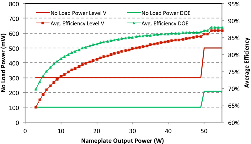
Figure 1. DOE proposed regulations vs. Level V performance for a 5V output EPS.
The need to reduce active-mode power consumption is somewhat obvious. What has not been so obvious is the need to minimize power drain in standby and no-load when products are essentially doing nothing. Several studies have been performed worldwide to quantify this consumption by domestic equipment and AC power adapters, with emphasis on its environmental impact. The International Energy Agency (IEA) estimates that five to 15 percent (depending on country) of household electricity consumption is wasted in these modes and accounts for one percent of the global CO2 emissions. This resulted in tighter regulations and new industry-specific initiatives encouraging manufacturers to develop more efficient AC/DC designs. External power supplies (EPSs) have been in the forefront of these energy-saving discussions because it is the cumulative effect due to the billions of units sold each year and they do not have an on-off switch. Left plugged in the wall, these chargers continually consume power even when the device it powers is disconnected. Consumers are also becoming increasingly interested in green products. Many equipment manufacturers are developing designs that use energy more efficiently and marketing it to give them a competitive edge. The ultimate goal is to reduce the device's power drain to zero when not in use. The key is to achieve this performance at a reasonable cost. Regulations driving green performance Many global regions are introducing mandatory and voluntary limits for no-load power consumption and operating efficiency of EPSs. In the US the main drivers are California Energy Commission (CEC), which is mandatory, and the voluntary Energy Star program from the US Environmental Protection Agency (EPA). Energy Star defined the International Efficiency Marking Protocol (Level I-V) in 2006, which set the minimum efficiency and no-load power consumption levels for EPSs. Similarly, the European Commission has issued the Energy Using Products (EuP) Directive Lot 6 applicable for standby and off-mode losses of EuPs. In 2011, they lowered this level to 300 mW for adapters ? 51W or 500 mW for adapters > 51W. The IEA 1-Watt initiative to reduce standby power use by any appliance to not more than 1W in 2010, and 0.5W in 2013 has driven regulations in many countries and regions. In March 2012, the U.S. Department of Energy (DOE) issued a Notice of Proposed Rulemaking (NOPR) that lays out the first mandatory regulations for external battery chargers and further tighten regulations on EPSs. In the Level VI standard, the proposed regulations significantly tighten and expand the range of the current minimum efficiency requirements. The proposal contains seven new product classifications (B-E, X, H & N), and multiple output and >250W EPSs. In Figure 1 the performance requirements per this new regulation for a 5V output direct operation EPS (Class C) are compared with the current Level V standards.
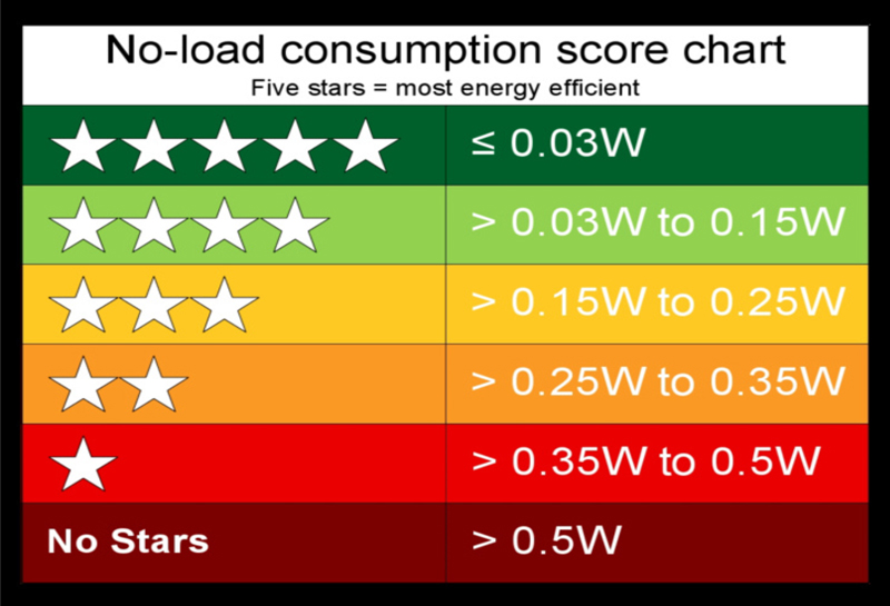
The European Commission's Integrated Product Policy Program (ECIPP) and the world's top mobile phone makers introduced a voluntary energy rating system for mobile phone chargers, making it easier for consumers to determine which ones use the least energy at no load. The rating system ranges from five stars (<30 mW no-load power) for the most efficient chargers down to zero stars for chargers consuming the most energy (see Figure 2). There is a strong momentum building in the EPS market to push this 30 mW no-load performance point beyond the mobile charger market to higher power applications like tablets, ultra books, notebook, TVs, and other electronics. Minuscule power consumption within the power supply leaves much more power available for use by electronic systems designed to comply with standby power limits. For example, a power supply that consumes only 10 mW at no-load allows a higher margin for other leaky circuit components (such as input filters, capacitors, and bias components), while still providing the power required to support system standby activities like remote activation, LCD display panel, and the like.
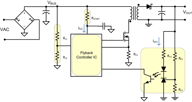
Understanding no-load power losses The flyback topology remains the preferred choice for non-PFC EPS adapters due to its simplicity and low cost. Four key elements that contribute most to the system no-load power losses are highlighted in Figure 3: startup bias resistor, input line sense network, IC bias power (no-load current, switching frequency, etc), and feedback bias power. An electromagnetic interference (EMI) filter, snubber and MOSFET switching losses make up the remaining no-load power consumption.
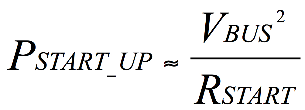
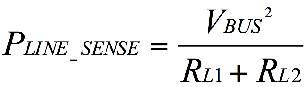
Resistive start-up circuits are used in power supplies to start the controller IC when the AC input is first applied. There is a tradeoff between start-up time and no-load power. To decrease start-up time, RSTART must be lowered, which increases no-load power. (See Equation 1) Most designs also require AC line brownout protection to disable the power supply and prevent over-heating (if thermistor thermal protection is not included). This function usually is implemented with high-voltage (HV) line-sensing resistors that add to the no-load power consumption. (See Equation 2)
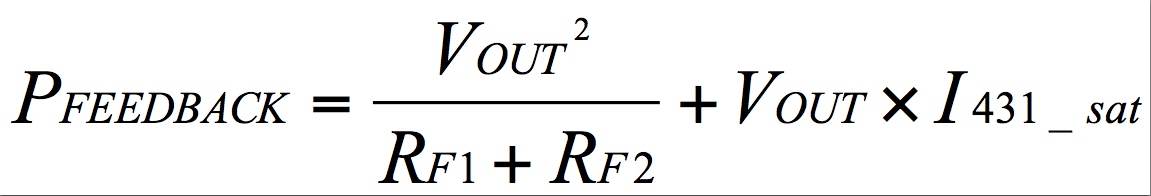
Typical AC/DC power supplies have a feedback network to send the error signal from the isolated secondary to the primary-side controller via a TL431 shunt regulator and optocoupler. There are two fundamental issues with this approach: a) the TL431 needs a minimum cathode bias current (I431_MIN) under all conditions; and b) the standard optocoupler configuration consumes the most current at no-load conditions (I431_SAT). The overall losses from this feedback network are shown is Equation 3. Note that this loss becomes a significant portion of the no-load power budget when the converter output voltage increases. The IC current consumption during no-load ICCNO_LOAD (quiescent current + the averaged MOSFET gate-drive current) is accounted for in Equation 4. For example, a recent state-of-the-art 5V/2A USB wall charger was tested for no-load power consumption and measured 121 mW at 230V AC.

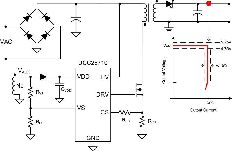
Green power: low no-load power + high average efficiency How does a constant-voltage, constant-current (CVCC) controller with primary-side regulation (PSR) like the UCC28710 [1] simplify AC/DC designs and help achieve best-in-class efficiency with no-load power performance? The controller regulates the output voltage and output current within five percent accuracy without optocoupler feedback. It processes information from the primary power MOSFET and an auxiliary winding on the power transformer for precise CVCC control (see Figure 4). The UCC28710 implements three key features to support ultra-low no-load power consumption: an internal 700V JFET start-up switch, dynamically-controlled operating states, and a tailored modulation profile. The 700V JFET allows the IC to cut off the current path from the HV DC bus after the IC is turned on and has a leakage of less than 1 μA in the off state. The controller enters smart sleep modes as the converter load decreases and reduces its average current consumption down to 95 μA during no-load operation. The IC control algorithm modulates the converter switching frequency and primary current peak amplitude (FM and AM) to provide a wide dynamic operating range of output power to achieve ultra-low no-load power, and also maintains high conversion efficiency across line/load. Other green features include converter valley-switching to reduce MOSFET switching losses, and line under-voltage protection (quasi-brownout) without any direct line-sensing resistors.
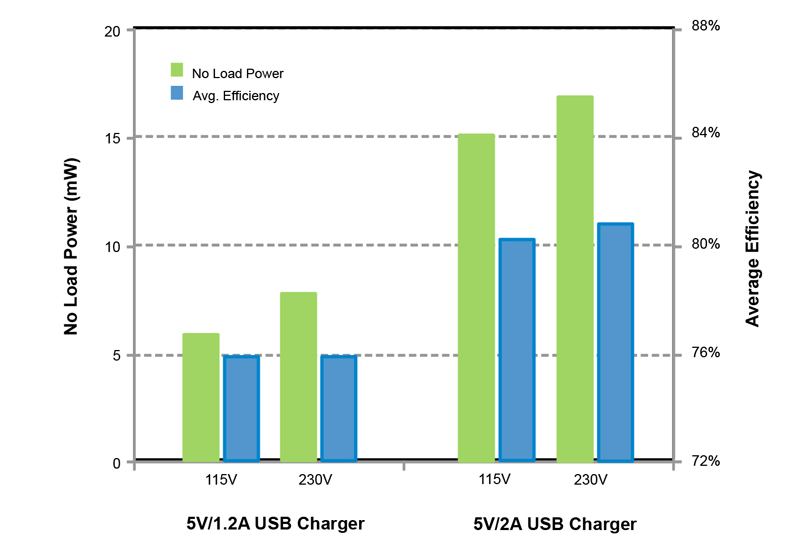
For example, two USB chargers were designed using the UCC28710: one at 5V/1.2A for smartphones, the other at 5V/2A for a tablet application. Test data for the two designs are summarized in Figure 5. The controller enables ultra-low no-load power consumption (8 mW and 17 mW respectively when operating at 230V AC), while the optimized modulation scheme also facilitates achieving high average efficiency. Please refer to references 2 and 3 for full test data and bill of materials for these designs. Efficiency can be further improved by implementing synchronous output rectification [4, 5]. Summary With billions of power supplies in use today that typically are left plugged in and unused for an average of 20 hours a day, the issue of no-load power is cumulatively huge with a correspondingly huge payback potential, if carefully addressed with industry regulations and smart power supply design choices. Devices like the UCC28710 green-mode flyback controller address this global need for green power supplies with the added benefit of offering a lower total component and solution cost. Texas Instruments References 1) UCC28710datasheet: www.ti.com/product/ucc28710 2) 5V/2A, <30 mW USB charger reference design: www.ti.com/tool/pmp8363 3) 5V/1.2A, <10 mW USB charger reference design: www.ti.com/tool/pmp4344 4) Adnaan Lokhandwala, "High-efficiency AC adapters for USB charging," Analog Applications Journal, Texas Instruments, 1Q12: www.ti.com/lit/an/slyt451/slyt451.pdf 5) TI Adapter Power Solutions: www.ti.com/adapterpower