Creating colorful, bright, and functional LED lighting
RGB LEDs are used in projector, architectural, display, stage and automotive lighting systems that require efficient, bright output. To produce predictable colors from an RGB LED, each of its component LEDs (red, green and blue) requires individual, accurate dimming control.
High end systems can use an optical feedback loop to allow a microcontroller to adjust the LEDs for color accuracy. Adding a white LED to an RGB LED to produce an RGBW LED extends the hue, saturation and brightness values available in the color system. Each RGBW LED requires accurate dimming of four component LEDs. Two RGBW LEDs require eight “channels.”
Driving differences
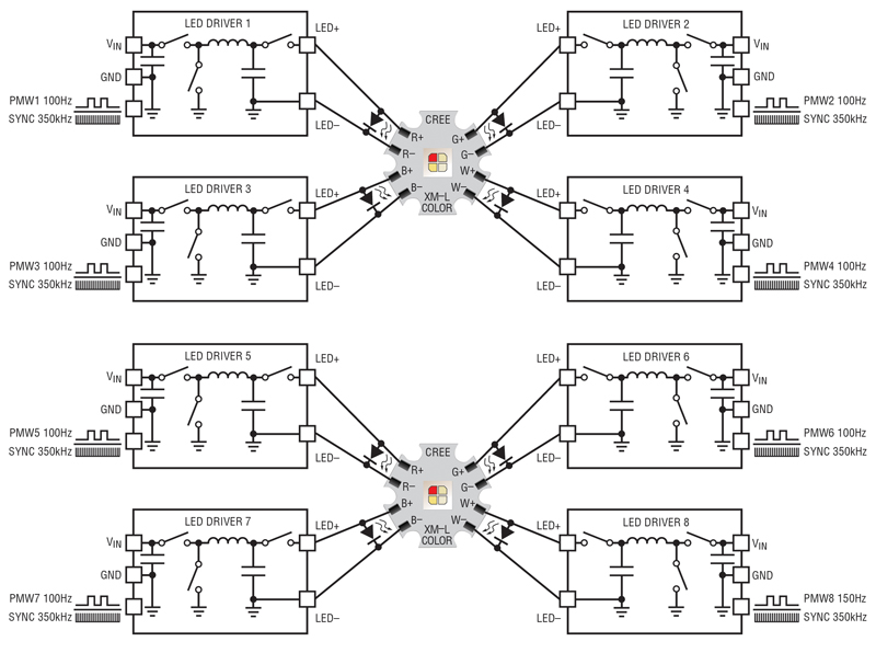
There are various ways to drive RGBW LEDs for color and brightness control. One way to drive and dim RGBW LEDs is to use four separate LED drivers, one for each color (R, G, B and W) as shown in Figure 1a. In such a system, the LED current, or PWM dimming, of each individual LED or string is driven by separate drivers and control signals. In this solution, though, the number of LED drivers increases quickly with the number of RGBW LEDs. Any lighting system with a significant number of RGBW LEDs requires a substantial number of drivers and synchronization of the control signals to those drivers.
Click image to enlarge
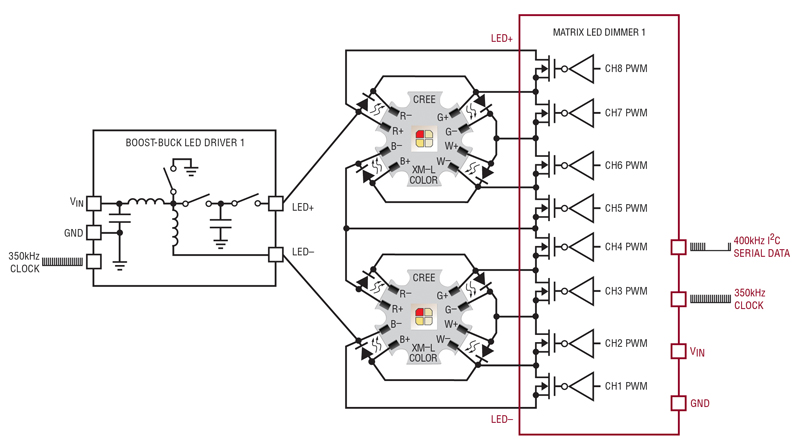
Figures 1a and 1b (1a) Eight separate LED drivers and PWM signals can be used to drive two RGBW LEDs in a high power color-mixing application or (1b) a single boost-buck LED driver and matrix LED dimmer with serial communications can be used for a much smaller and compact solution.
A much simpler (and more elegant) approach is to drive all of the LEDs with a single driver/converter at a fixed current, while using a matrix of shunting power MOSFETs to PWM dim the individual LEDs for brightness control. The matrix dimmer and single LED driver shown in Figure 1b reduces the circuit size of the Figure 1a solution. Furthermore, a single communications bus to control the matrix LED dimmer makes RGBW color-mixing LED systems relatively simple and compact, while driving high current RGBW LEDs with accurate color and brightness control.
Click image to enlarge
Figures 1a and 1b (1a) Eight separate LED drivers and PWM signals can be used to drive two RGBW LEDs in a high power color-mixing application or (1b) a single boost-buck LED driver and matrix LED dimmer with serial communications can be used for a much smaller and compact solution.
The LT3965 matrix LED dimmer enables such a design, as shown in Figure 2. Each LT3965 8-switch matrix dimmer can pair with exactly two RGBW LEDs, allowing control of the individual brightness of each LED (red, green, blue and white) in PWM steps of 1/256 between zero and 100% brightness. Two-wire I2C serial commands provide both color and brightness control to all eight channels. I2C serial code to the matrix LED dimmer IC determines the brightness state of all eight LEDs and can check for open and short LEDs in case of a fault.
Click image to enlarge
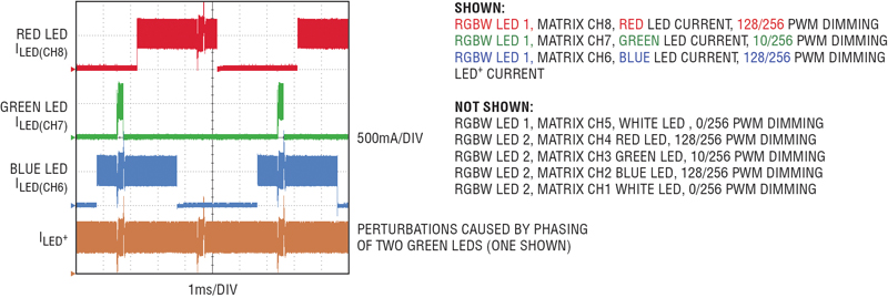
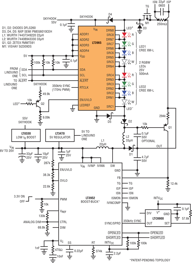
Figure 2. The RGBW 500mA LED currents are PWM dimmed and phased by the LT3965 matrix dimmer to create colors and patterns. The LT3952 boost-buck converter/LED driver easily keeps up with the rapid changes in LED voltage as individual LEDs are PWM dimmed.
Since each RGBW LED is designed as a single point source, the red, green, blue, and white light combine to produce color variety, with saturation, hue, and brightness control. Each LED can be set in 1/256 steps between zero (0/256) and 100% (256/256) with the high-speed LT3965 matrix dimmer.
Accurate 0–256 rgbw color and brightness control
RGBW LEDs can produce accurate color and brightness with PWM dimming of the individual component red, green, blue and white LEDs. Individual PWM brightness control can support 256-to-1 or higher dimming ratios. An alternative to PWM dimming is to simply reduce the drive current for each LED, but accuracy suffers in this method, allowing only 10-to-1 dimming ratios, and incurring color drift in the LEDs themselves. A matrix dimming approach using PWM dimming outperforms drive-current schemes in accuracy of color and brightness.
The bandwidth and transient response of the LED driver (the source of the 500mA LED current) affects the color accuracy. With over 10kHz crossover frequency and little or no output capacitor, the compact boost-buck converter in Figure 2 reacts quickly to changes in the number of driven LEDs as the matrix dimmer turns its switches on and off.
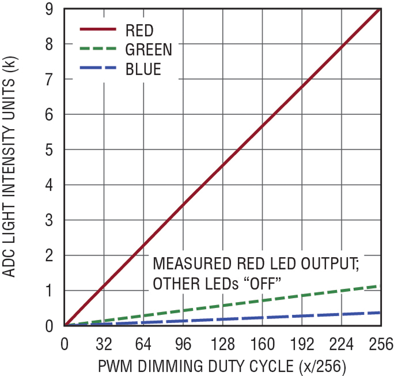
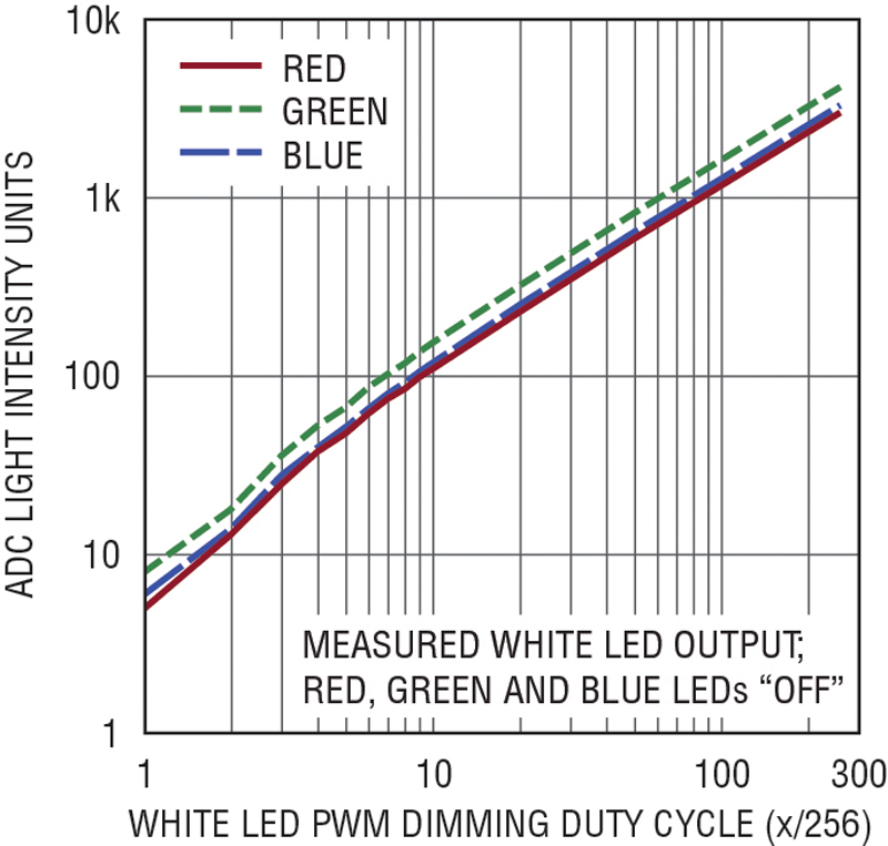
To illustrate how important this is to accuracy, red, green and blue LEDs are run separately at different PWM duty cycles and measured for light output with an RGB optical sensor. The results in Figure 3 show uniform slopes of each color from 4/256 to 256/256, with a slight change in slope below that. Of course, red, green and blue LEDs are not perfect in their color, so some color from other bands sneaks out even when only one is driven. Overall, this is a highly accurate system.
Click image to enlarge
Figure 3a. Red, green, blue, and white brightness control versus 0–256 (out of 256) PWM dimming duty cycle controlled by the matrix LED dimmer when paired with the LT3952 boost-buck LED driver in Figure 5.
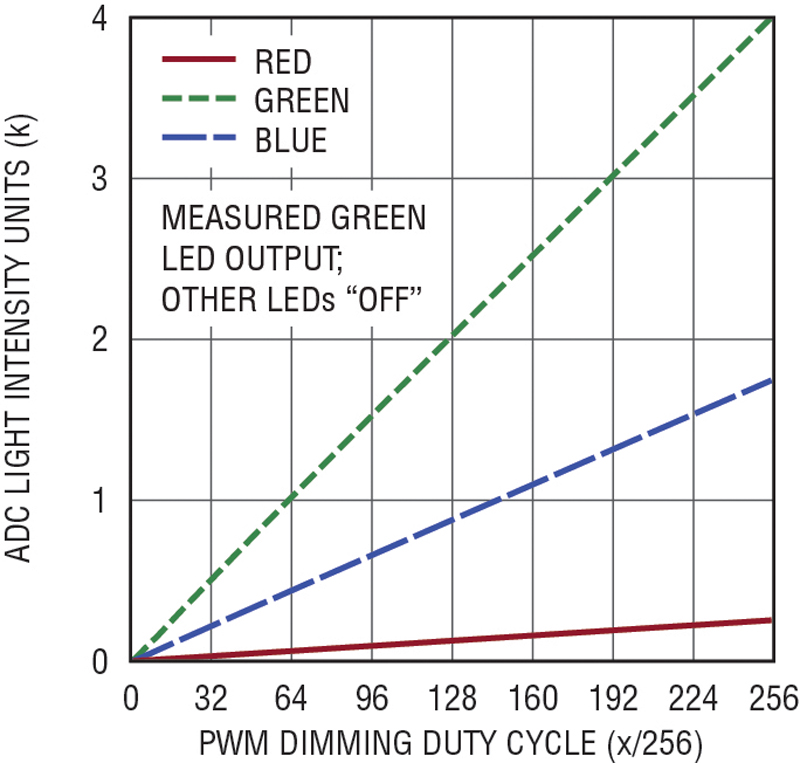
Figure 3b. Red, green, blue, and white brightness control versus 0–256 (out of 256) PWM dimming duty cycle controlled by the matrix LED dimmer when paired with the LT3952 boost-buck LED driver in Figure 5.
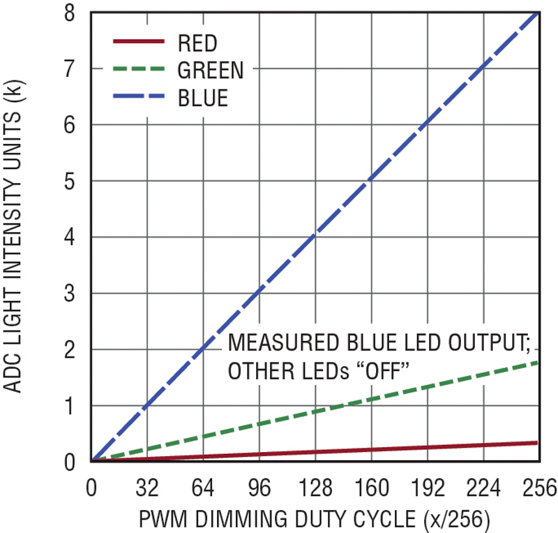
Figure 3c. Red, green, blue, and white brightness control versus 0–256 (out of 256) PWM dimming duty cycle controlled by the matrix LED dimmer when paired with the LT3952 boost-buck LED driver in Figure 5.
Click image to enlarge
Figure 3d. Red, green, blue, and white brightness control versus 0–256 (out of 256) PWM dimming duty cycle controlled by the matrix LED dimmer when paired with the LT3952 boost-buck LED driver in Figure 5.
Accuracy can be improved down to 1/256 PWM dimming using a very high bandwidth (>40kHz) buck converter LED driver, but that involves either the expense of adding another step-up converter to create a regulated, greater than 30V output voltage, or having an input voltage source above 30V. Unless a high level of accuracy at extremely low light is necessary, there is little reason to forgo the Figure 5 boost-buck’s versatility, simplicity and compact size by adding an extra converter.
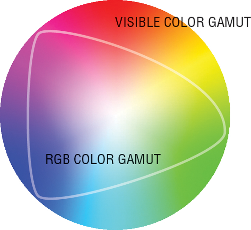
The matrix dimmed RGBW LED color mixer system described here achieves a broad color gamut, as shown in Figure 4. Adding additional colors, such as amber, can expand the gamut. RGBWA LEDs (with an amber LED component) can produce deep yellows and oranges that RGBW LEDs cannot. These LEDs can also be driven with the matrix dimmer, but the eight channels of the matrix dimmer match well to two RGBW LEDs.
Click image to enlarge
Figure 4. RGB LEDs feature a wide color gamut. Adding white is one way to simplify the algorithmic mixing of specific colors. In some mixing schemes, white is used to change the saturation, while red, green and blue set the hue.
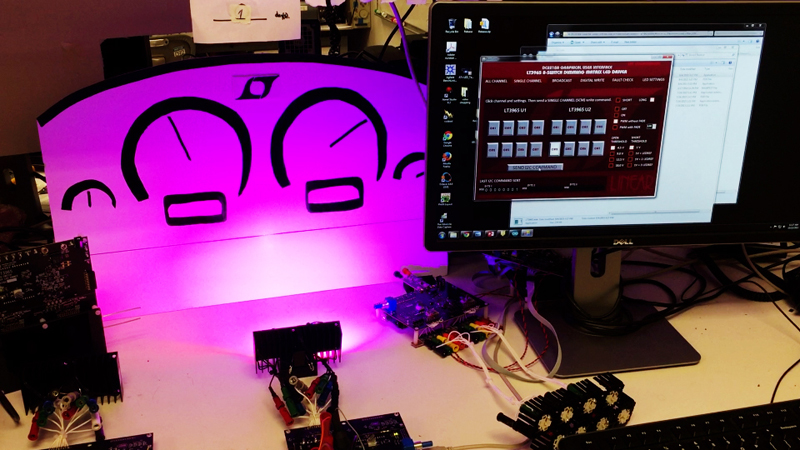
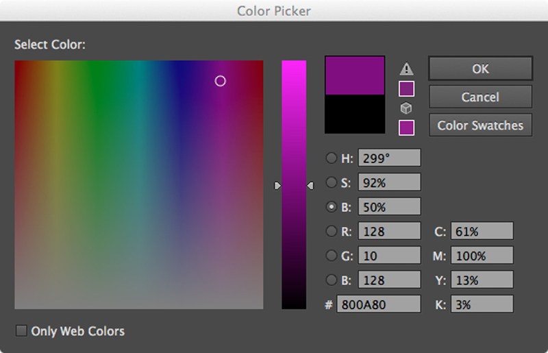
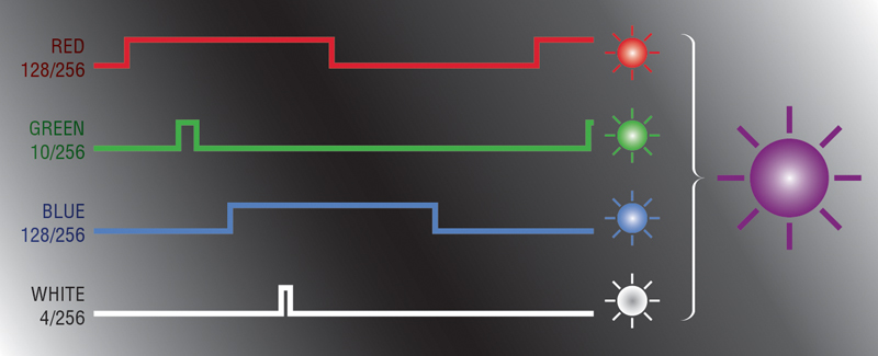
The 256-level dimming scheme of the LT3965 easily translates to typical RGB paint programs and common color-mixing algorithms. For instance, if you open a standard PC paint program, you will see that colors are mixed using a 256-value RGB system, as shown in Figure 6a. For example, the LED current waveforms in Figure 6b produce purple light from an RGBW matrix LED system controlled by a basic PC-based paint program. Because the design described in this article produces accurate current drive and PWM control, RGBW LEDs can be predictably color-calibrated by adjusting the duty cycles of the component LEDs, easily accounting for inherent variations in LED brightness.
Click image to enlarge
Figure 6a. Colors can be chosen using a standard PC-based color picker. The 0–256 values used by the matrix dimmer can be related to the 0–255 values used in typical RGB systems. For instance, RGB(128,10,128) produces a purple hue. As can be seen in the photograph below, the matrix dimmer can produce predictable colors with a real RGBW LED, simplifying the work of a lighting designer. (6a) Choose a color. (6b) The RGB values correspond to the LT3965 LED matrix dimming ratios. (6c) Use your PC to set the dimming values, and see the results.
Click image to enlarge
Figure 6b. Colors can be chosen using a standard PC-based color picker. The 0–256 values used by the matrix dimmer can be related to the 0–255 values used in typical RGB systems. For instance, RGB(128,10,128) produces a purple hue. As can be seen in the photograph below, the matrix dimmer can produce predictable colors with a real RGBW LED, simplifying the work of a lighting designer. (6a) Choose a color. (6b) The RGB values correspond to the LT3965 LED matrix dimming ratios. (6c) Use your PC to set the dimming values, and see the results.

Click image to enlarge
Figure 6c. Colors can be chosen using a standard PC-based color picker. The 0–256 values used by the matrix dimmer can be related to the 0–255 values used in typical RGB systems. For instance, RGB(128,10,128) produces a purple hue. As can be seen in the photograph below, the matrix dimmer can produce predictable colors with a real RGBW LED, simplifying the work of a lighting designer. (6a) Choose a color. (6b) The RGB values correspond to the LT3965 LED matrix dimming ratios. (6c) Use your PC to set the dimming values, and see the results.
Matrix led color mixer with boost-buck
The matrix dimmer requires a suitable LED driver to power the string of eight LEDs from a variety of inputs: standard 12V ±10%, 9V–16V (auto) or 6V–8.4V (Li-ion). One such solution is the LT3952 boost-buck LED driver, which both steps up and steps down input-to-LED voltage, while providing low ripple input and output current. With little or no output capacitor in its floating output topology, it can react quickly to changes in LED voltage as the individual LEDs are PWM-dimmed on and off to control color and brightness.
The LT3952 500mA boost-buck LED driver shown in Figure 5 pairs with the LT3965 8-switch matrix LED dimmer and two RGBW 500mA LEDs. This new boost-buck topology gracefully operates over the entire range of zero-to-eight LEDs in series, with a voltage of 0V to 25V. The instantaneous series LED voltage changes, determined by which, and how many LEDs are enabled and disabled by the matrix dimmer at any given moment. The 60V OUT voltage of this converter/topology (a sum of VIN and VLED), and the converter duty cycle, are rated for the full input range of 6V to 20V and output range (LED series voltage) of 0V to 25V at 500mA.
Click image to enlarge
Figure 5 Together with the LT3952 boost-buck LED driver, the LT3965 matrix LED dimmer controls individual colors on two 500mA RGBW LEDs for serial-controlled color and patterns.
The matrix dimmer controls LED brightness by shunting the LEDs with parallel power MOSFETs. The LEDs do not need to be connected to ground with either the floating output boost-buck LED driver or with the matrix LED dimmer. As long as the VIN pin of the LT3965 is connected to SKYHOOK, which is at least 7.1V above LED+, all of the shunt MOSFETs work properly. SKYHOOK can be created with a charge pump from the switching converter or it can be supplied with a regulated source that is at least 7.1V greater than the highest expected LED+ voltage (in this case, 20V VIN max plus 25V LED max). The tiny LT8330 boost converter in a 3mm × 2mm DFN is a good choice to generate SKYHOOK.
An optional external clocking device is used to synchronize the system at 350kHz, which is suitable for automotive environments, relatively efficient and allows the use of compact components. Although this system could just as well run at 2MHz (above the AM band), 350kHz (below the AM band) enables this boost-buck converter to regulate without pulse-skipping when all LEDs are shorted by the matrix dimmer and the LED string voltage drops to 330mΩ • 500mA • 8 = 1.3V. This frequency also supports high dimming ratios without visible LED flicker.
Start-up sequence with LEDs on or off
The matrix LED dimmer system can be set to start with all of the LEDs on or off. Starting up with all of the LEDs off allows them to fade on softly or to start at a programmed color and brightness, such as green-blue at 10% brightness. If all of the LEDs start with full 500mA current before the serial communications begin telling the dimmer what to do, then full bright “white” light may be observed before serial communications start.
With either start-up method, the LT3965 should be powered up before it receives I2C serial communications, or the initial communications may be lost when it performs a power-on reset (POR). The POR occurs when the EN/UVLO pin crosses above the 1.2V threshold. Since this voltage is based on SKYHOOK being at least 7.1V above LED+, this can occur at any time after a high SKYHOOK voltage is applied, such as 55V from a small boost regulator, or it can happen after a charge-pumped voltage from the LT3952 switch node is high enough to create SKYHOOK. In the case of a charge-pumped SKYHOOK, the LED current may be present before the charge-pumped SKYHOOK, so the LEDs light up before the LT3965 switches can turn the LEDs off. This is a simple solution for a designer who would like the LEDs to turn on full brightness to start.
To start the LEDs off, SKYHOOK must be present at a high voltage before the LT3952 is turned on. As shown in Figure 6, if the PWM pin is held low during start-up, the LT3952 will not start up until it is commanded to do so by an external source, such as the master microcontroller. The microcontroller can send I2C setup commands to the LT3965 once SKYHOOK is present and set up its switches to the LED OFF position before current is flowing to them. Then, after setup, the LT3952 PWM can be asserted and the current begins to flow through shorted LT3965 switches, with the LEDs off. After this, a fade start can occur, or the LT3965 dimmer can jump to a particular color or brightness.
Upon a reset, the PWM of the LT3952 must be pulled low again to turn it off and restart in the LEDs off position. In the case of Figure 5, a simple micropower boost such as an LT8330 can supply 55V from the 6V–20V input. The microcontroller receives a signal that LT3965 is powered up and ready to receive serial communications by asserting the ALERT flag. Before any of the switches are shorted out, zero current through the LEDs shows up as zero voltage across the switches—interpreted and reported as a short-circuit fault. Only after the LT3965 is powered up by SKYHOOK is the flag asserted.
The LT3965 matrix LED dimmer such as the LT3965 can be paired with a boost-buck LED driver to form an accurate-color RGBW LED color mixer system. With the LT3952, it can be used to drive two RGBW LEDs at 500mA with 350kHz switching frequency from a 6V to 20V input. This versatile system can be powered with automotive batteries, 12V power or Li-ion batteries. High color accuracy results from the fast transient response of the patent-pending boost-buck LED driver topology and predictable dimming control via the 256:1, I2C-controlled matrix system. It can be set up to start up with all of the LEDs off and can fade to start or jump to a particular color. Although not required, optical feedback (via microcontroller) can be added to improve color accuracy.