
It’s a testament designers of power architectures that datacenters use barely more energy now than in 2010, despite workloads increasing nearly ten-fold
Figure 1: Early datacenters used distributed AC for each shelf in a rack
The measure of datacenter energy efficiency is ‘Power Usage Effectiveness’ or PUE, and the best ‘hyperscale’ installations achieve a figure of about 1.1, or 100 W lost in cooling, distribution and power conversion for every kW used by the IT equipment. As best practices trickle down to smaller datacenters, the potential overall gains get used up and further demand in capacity will start to reflect in proportional increase in energy demand, unless better PUE can be achieved. Additionally, the pace of change is increasing with IoT and AI dramatically increasing compute-demand.
As a result, designers feel pressure to reduce losses further for both economic and environmental reasons, and there are new techniques that show promise, but it’s worth a recap of the achievements so far.
Evolution of datacenter power distribution
The modern datacenter has its origins in telecommunications switching installations where -48 V was the standard supply, generated from AC mains ‘rectifiers’ backed up by lead acid batteries. Relays operated directly from this supply and 48 V was routed out along lines to subscribers. As electronics appeared, mains AC was routed to servers, each with its own AC/DC power supply, which generated typically 12 V, down-converted further as necessary. This presented safety problems, with reinforced insulation systems required at every circuit board, and the high voltage AC was inconvenient and expensive to be bussed around a cabinet. With dual AC supplies often required for redundancy, cabling proliferated (Figure 1). Also, battery back up had to be duplicated within each shelf or implemented as a central UPS.
A development was to generate 12 V centrally and bus this around a cabinet to the individual shelves in a ‘Centralized Power Architecture’ or CPA. Many end loads operated directly from 12 V and down-conversion to 3.3 or 5 V for logic was relatively simple. As current demand increased at this low voltage, losses became unacceptable and an obvious evolution was to increase the bus voltage back to 48 Vdc to each shelf. Down-conversion to ever-reducing end-load voltages was achieved with multiple isolated DC/DC converters at the end loads. This first ‘Distributed Power Architecture’ (DPA) was an expensive solution however when multiple rails were needed, so ‘hybrid’ schemes came into use with one isolated converter on a board outputting 12 V, feeding several non-isolated ‘point-of load’ or PoL DC/DCs for lower voltages still. This became the standard ‘Intermediate Bus Architecture’ (IBA), common today.
Working towards higher efficiency
Given the IBA arrangement, power converter designers have taken advantage of all techniques available to improve efficiency: diode rectifiers are replaced by MOSFETS, resonant topologies are used for higher efficiency and power density, and latest wide band-gap semiconductors used for their low losses. It was appreciated that if the point of load converters could have a wide input range, the intermediate bus converter, powered from a nominally constant 48 V, could be un-regulated and drop the voltage in a fixed ratio, typically 4:1 giving a nominal 12 V output. This enabled simpler, smaller and more efficient bus converters. ‘Hybrid’ converters have also appeared, pioneered by Flex Power Modules [2], with their ‘HRR’ technique, which is a ratio converter up to a certain input voltage which then limits and regulates the output for higher input voltages. This restricts the bus converter output voltage range so following PoL converters can be designed for better efficiency, while limiting the bus converter range of control duty cycle required in turn improving its efficiency, which is designed to peak at the nominal input voltage and typical load. Variants in the Flex Power Modules PKU-D series are available with the HRR feature and Figure 2 shows the output characteristics compared with a fixed ratio (5:1) converter. The variant shown has a nominal 54 V input.

Click image to enlarge
Figure 2: The Flex Power Modules HRR hybrid ratio regulation technique visualized
The HRR technique also gives improved transient response compared with a fixed ratio type which can pass input voltage transients and ripple directly to the load.
Traditional IBA with four conversion stages
The IBA approach has entailed at least four stages of power conversion: mains AC to power-factor-corrected high voltage DC, isolation and down-conversion to 48 V, 48 V to isolated 12 V and then 12 V to end load voltages. The multiple stages each inevitably have some loss, so the architecture is continually re-examined to look for any optimization. One possibility is to make the 48 V to 12 V conversion without isolation, which is only present for functional reasons rather than safety. If this is acceptable in the system architecture, an unregulated, non-isolated switched capacitor converter can provide better than 98% efficiency, such as the new digital BMR310 product from Flex Power Modules. This provides over 1 kW peak from a baseplate-cooled package, just 58.4 x 25 x 9.9 mm. The product uses a proprietary technology: the zero-voltage switching, Switched Capacitor Converter (ZSC).
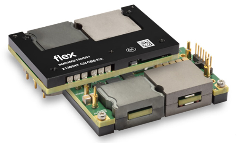
When bus converter regulation is required however, this would previously have resulted in efficiency compromise, but there is a new generation of non-isolated 48 V to 12 V regulated converters that approaches the 98% barrier such as the BMR350 from Flex Power Modules (Figure 3). This part has a peak power rating of 1200 W and is parallelable up to three units. It has a DOSA-compatible digital interface for control, monitoring and protection and has a novel ‘event data recorder’ or ‘black box’ function for internally storing fault event data. The baseplate-cooled module is just 58.4 x 36.8 x 12 mm.
Click image to enlarge
Figure 3: The regulated BMR350 IBA converter from Flex power Modules is >98% efficient
Direct Conversion from 48V to end voltages
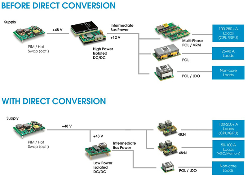
Another development is the introduction of converters that perform ‘Direct Conversion’ from 48 V to core voltages down to as low as 0.5 V with isolation, replacing the combination of intermediate bus converter and PoL. The technique yields a valuable 2-3% gain over the 48 V to 12 V to sub-1 V approach. A good example is the BMR481/482 family of parts from Flex Power Modules which can deliver up to 110 A from a surface-mount package, just 30 x 12 x 14 mm. Up to five, smaller ‘satellite’ modules can be paralleled for greater than 600 A total capability. Not only is efficiency improved over the traditional approach but there is also a significant reduction in board space requirements.
Click image to enlarge
Figure 4: Traditional and ‘Direct Conversion’ arrangements compared
PoLs are now extremely compact
If the PoL converter approach with an IBC is taken, perhaps because there are multiple different end voltages to generate or there is anyway a need for a 12 V rail, latest PoL designs in the form of Voltage Regulator Modules (VRMs) have become very compact. The BMR510 from Flex Power Modules for example, has a footprint of less than 1 cm2 but delivers up to 140 A peak from a wide 4.5-16 V input range. These LGA parts with top-side cooling are the power stage of a PoL converter with the controller designed into the user’s motherboard, typically mounted on the reverse side of the PCB. This arrangement provides the optimum use of space for power-intensive applications such as AI.


