Getting to market faster
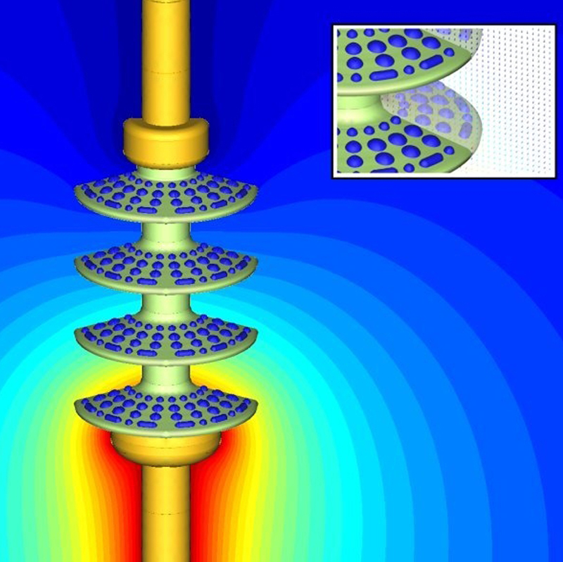
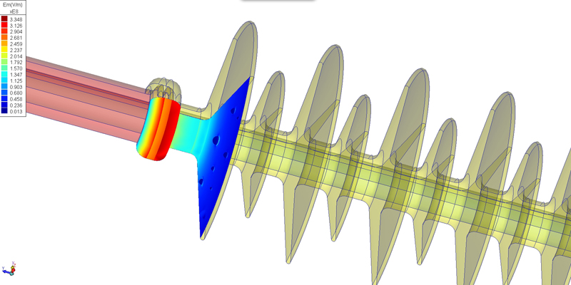
Analysis of insulator covered with water droplets
Using modelling software in this current economic market speeds up delivery time by increased accuracy at an early stage in the design process. The majority of engineering designers today across all power markets, from industrial to automotive, use some degree of modelling software to speed up the design process prior to prototyping and manufacture. With even the most oil and gas dependent countries placing greater impetus on green energy, the importance of efficient power management is permanently high on the agenda. In the past designs were tested by building a physical prototype and trying to measure their performance. The drawback of this approach is twofold - firstly, it is costly to produce prototypes and secondly, little design insight is gained. The first problem is obvious but the second, whilst not so obvious, is ultimately more important as it is only by the simulation of a design that great leaps forward can be made. For example, when building a prototype test model the designer can often measure bulk quantities such as voltage or temperature. However, simulation tools go far beyond these measureable quantities, allowing the engineer to �see' the invisible, and no amount of prototyping can replicate this. The data accrued from the software can then be used to maximise performance alongside reducing materials and the costs associated with them. This is, in general, the ultimate use of any design tool - to improve a design by minimising cost, maximising reliability and optimising parameters. To do this, design software should allow users to change parameters, such as dimensions and materials, to establish how they affect the ultimate performance. Software with built in parametric features allow the user to change models without learning a complicated scripting language. This means simulations that may require hundreds of solutions to find the optimal design can be achieved with a very small learning curve. For designers not using simulation tools daily this is especially important as no relearning is required every time a solution to a new problem is needed. As an example, when designing products that require power, which is practically everything nowadays, it is important to initially be able to calculate the heat density volume. Having established that, it is then necessary to be able to minimise the amount of heat produced as the result of electrical current passing through a conductor, and next to manage that heat to minimise any cooling energy requirements. Electrical energy is not conserved; a proportion of it is converted into heat caused by eddy currents. This creation of heat through ohmic and or dielectric losses is highly important to the design and may ultimately determine its performance. Using simulation software for special modelling techniques such as Boundary Element Method (BEM) for electrical field calculation and Finite Element Method (FEM) for thermal analysis makes finding the solution for energy conservation much more simple and time efficient.
When using simulation software it is important to select the best field solver for your specific problem and using both FEM and BEM solvers gives an independent verification of the results. To simulate an electromagnetic problem, Maxwell's equations can be solved in either integral or differential form. Typically, the integral solution is associated with the Boundary Element Method (BEM) and the differential form with the Finite Element Method (FEM). As both methods are solving the same physical problem, the results from both should be the same. The two solution methods are completely different. So whilst one method might be the ideal solution for one type of problem it will be totally wrong for another. Ideally both methods should be available for the designer to select which method will give the best result alongside the least amount of user input time with the fastest computation time. In general, the boundary element solution is the best approach if the problem is linear with a large open region to handle. The boundary element approach, however, can lose some of its lustre when solving highly non-linear material properties. Certain classes of transient analysis are not readily handled by the BEM method, so for many of these problems the FEM is a superb method. The hybrid approach, where part of the problem is solved with FEM and the remainder solved with BEM would typically be the ideal solution. However, care must be taken when using hybrid methods as this can greatly increase the solution times for some problems. So, the question is not which is better, FEM or BEM, but which method is best suited for a specific application. To undertake any simulation, the physics of the problem must be input into the software. Normally the most difficult part of this is entering the geometry. The geometry for certain programs can be created using the geometric modelling tools within the software or can be input from the major CAD vendors like Solid Works; Solid Edge, Inventor or Pro E. Normally geometry created with these tools is not precise enough for solving the problem but Integrated Engineering Software provides healing tools to prepare the geometry for either a FEM or BEM mesh. One major question when simulating a design is whether to proceed in two dimension or three dimensions. As the real world is always 3D, ideally all problems would be solved in this way. However, most designers usually work in 2D due to the greater ease of inputting data and the radically faster solution times. To optimise a design thousands of solutions are often required and this is normally only practical for 2D models as the full equivalent 3D models can take hundreds of times longer to solve. As an added level, for coupled field problems, such as combined magnetic and thermal, the magnetic field may be solved in 2D but the thermal may require a full 3D solution. As desktop computing has progressed including the time dimension has started to become practical, meaning that with the three spatial dimensions some practical solutions can be obtained for the full 4D world. As more processors and greater memory becomes available, 4D problem solution will move into mainstream computations and will be useful to the designer for even more realistic simulation of true world conditions. Modelling permits an engineer to simulate innumerable options before beginning a build which in the past would have taken years, and now takes days. It is routinely used by companies wanting to create new energy efficient products, or to improve existing designs, as they can design and test product ideas prior to the manufacturing process, enabling them to modify the parameters to produce end products that minimise waste. Simulation software therefore reduces costs and minimises risks associated with physical prototyping - be it for bushings for major grid electricity or the battery in a cell-phone. It also allows companies to reduce design time and costs, spend less money on expensive prototypes, improve product performance, decrease time to market and ultimately increase profitability. www.integratedsoft.com


