Advanced Battery-Management ICs are Essential Elements Powering the Growth of Smart IoT Devices
New battery-protection system approach integrates a low-leakage, low-on-resistance load switch that extends all-important battery life while saving space
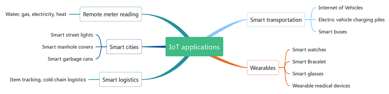
Figure 1: IoT Applications
The term Internet of Things, or IoT, was first developed in the late 1990s and was related to RFID technology. Over the two decades since being developed, IoT has flourished to include literally billions of nodes, each with its unique IP address. The notion of “smart” IoT is a relatively new development. These IoT devices are designed to create intelligent, interconnected systems to gather, process and utilize data to make informed, intelligent decisions. Adding intelligence to IoT devices requires the utilization of microcomputers, memory, communications modules like blue tooth and other components. Some examples of smart IoT applications include:
One thing all smart devices have in common is the increased power needed to perform these numerous functions; thus, more reliable and long-lasting battery power is essential in smart IoT applications. A critical tool in achieving extended battery life is the implementation of advanced battery-protection systems.
The Traditional Portable Battery-Protection Systems
In recent years, the demand for portability of sophisticated electronic systems has driven the need for various types and sizes of battery systems. These battery systemswere used to power laptop, mobile phones, digital cameras, portable digital assistants (PDAs), etc. Using a variety of battery chemistry materials, such as nickel metal hydride, lithium-ion, and lithium polymer could deliver more than 1A of continuous current.
As IoT applications proliferated, design challenges arose as portable devices increasingly required better protection of battery systems to prevent such problems as overcharge, overdischarge or excessive current drawing during short-circuit conditions.
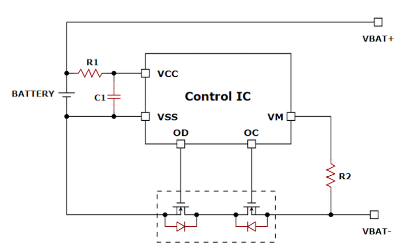
Figure 2 describes a traditional portable battery-protection system. It utilizes discrete N-channel power MOSFETs and a separate control chip to handle large current and power requirements. In Figure 2, even though one of battery positive or negative terminals is disconnected from the load, the battery remains connected across the VCC and VSS pins of the control circuit thereby constantly drawing current.
Click image to enlarge
Click image to enlarge
Figure2a & 2b:Traditional battery - protection system
NewApproach to ultra-Portable Battery-Protection Systems
The latest ultra-portable smart IoT devices for the consumer, medical device, industrial, asset tracking and other evolving electronic markets, are using different types of batteries that deliver significantly less current to the device. These ultra-portable battery systems require ultra-low current consumption to extend the useful life of the device before needing to be recharged.
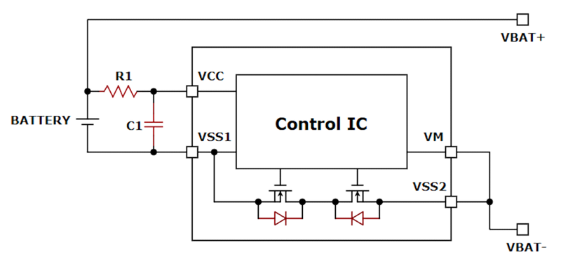
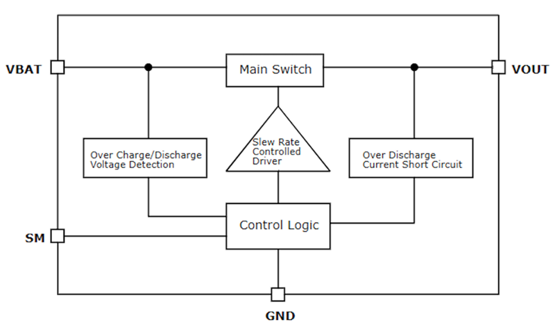
A new type of battery-protection system has been developed to meet the need for extended battery life in ultra-portable devices. The completely integrated power switch and battery-protection system, as shown in Figure 3, draws 1 µA -2µA during its operating mode and < 10nA leakage current when the device turns off.
This new approach utilizes an ultra-low leakage P-channel MOSFET as the main switch element operating in series with the positive terminal of the battery and directly monitoring the load current through the switch.
Click image to enlarge
Click iomage to enlarge
Figure 3a & 3b: Advanced integrated power switch and battery-protection system
Essential to this approach is using the industry’s most advanced smart IoT device battery protection devices, such as GLF Integrated Power’s GLF73xxx series products shown in Figure 3, to provide both overcharge and overdischarge protection. When a battery is charged past the overvoltage detection level, the IC’s charging switch opens at a preset delay time. If battery voltage decreases below its overdischarge level, the switch cuts off the battery’s power rail, resulting in ultra-low battery consumption. And when the load current reaches the short-circuit protection level, the IC switches and remains off to avoid potential system damage. The short circuit delay time also prevents false triggers that might open the switch.
Key Advantages of Advanced Smart IoT Battery-Protection
The key advantage of this integrated battery-protection approach is that the battery on the input side can be completely protected through the high-side switch both from over discharging, as well as from overcharging by having the battery charger connected on the switch output side. As a result, this battery-protection system reduces component count and saves a significant amount of space. This new IC with the accurate protection is in 1 mm x 1 mm WLCSP package. Its compact form factor makes it ideal for advanced wearables, connected medical devices, and other size constrained applications.
Four beneficial characteristics of this new design approach are:
1. This new battery protection system is very simple to use with almost no extra components, therefore reducing board space and manufacturing costs. It can be ready to work after a battery cell is attached. Since both operating current and shutdown current are extremely low, it can be placed on a main board of any smart IoT devices as well as in a battery pack.
2. This battery protection system is activated or turned on by applying a voltage (VON)mto the VOUT pin (See Figure 3). The VON comes from a charger IC output when a charger (or a charging function of a PMIC) is connected and starts working. When a battery cell is connected, the system doesn’t work until the VON is applied in order to prevent a battery cell from discharging immediately.
3. GLF73xxx family products share the common ground with the system so that this solid ground connection assures system stability and helps engineers to obtain reliable data during their system measurement and debugging.
4. A unique feature of Shipping Mode can greatly extend the battery life dramatically for warehouse storage and shipping -- especially long-duration shipping.
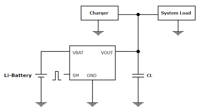
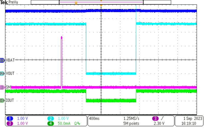
The figure 6 on the left shows the operation of shipping mode function.
1) Applying a pulse of 1.2 VMIN with 20 ms duration to the SM pin makes the IC turned off to enter the SM mode in preset 600 ms.
2) When the VON voltage is applied to VOUT, the IC resumes normal operation.
A deep sleep function of the IC in the battery-protection system allows disconnection of the battery from the system load, such as when finishing the final board test and placing the device into storage prior to shipment or starting shipping. A short pulse voltage will make system entering the shipping mode which puts an IC in deep sleep consuming almost zero current.
1) When the smart device enters deep sleep mode, especially those with a non-removable battery, will be protected from discharging during the shipping period without adding any extra peripheral circuitry.
2)This battery protection chip remains off state and consumes an ultra-low leakage current (ISD) until the VON voltage is applied to VOUT pin to release the system from Shipping Mode.
Application Example
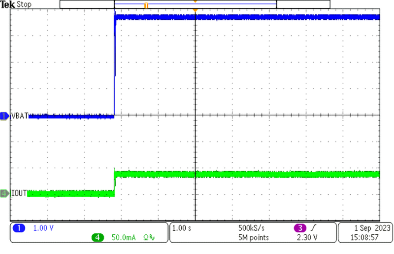
1. Different behaviors when connecting a battery cell to systems.
The figure 4 shows the moment when a battery cell is attached to the traditional battery protection system in Figure 2.
When a battery cell is attached, the battery pack supplies power to system immediately.
Click image to enlarge
Figure 4: A battery cell is attached to traditional battery protection system
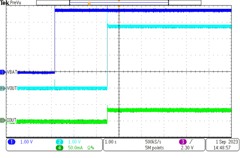
The figure 5 on the left shows the operation of battery protection IC like GLF73xxx family products.
1). When a battery cell is attached, the GLF73xxx ICs is not activated. The VOUT node remains grounded.
2). When an on voltage (VON) is applied to the VOUT pin, the IC is activated to be ready to supply power without any electrical noises.
Click image to enlarge
Figure 5: A battery cell is attached to Battery protection system of GLF73xxx
2. Shipping Mode
The figure 6 on the left shows the operation of shipping mode function.
1) Applying a pulse of 1.2 VMIN with 20 ms duration to the SM pin makes the IC turned off to enter the SM mode in preset 600 ms.
2) When the VON voltage is applied to VOUT, the IC resumes normal operation.
Click image to enlarge
Figure 6: GLF73xxx Shipping Mode function
What’s Next in Smart IoT Power
Energy harvested from light or thermal sources can be stored in ultracapacitors to replace or supplement the power from rechargeable batteries. Advances in energy harvesting technologies are starting to have an impact on wearable smart IoT devices. The application of this technology demands the use of high-performance battery-protection ICs that exhibit very low (µA) operating mode and low nA leakage when in the OFF state. An integrated battery-protection design approach is well-suited to meet these design requirements.
Conclusion
The rapidly expanding and evolving smart IoT ecosystem has changed the requirements for protecting rechargeable batteries and limiting battery discharge during standby states. Among the most significant requirements for smart IoT devices is battery life. Moreover, the emergence of new rechargeable battery technologies and energy harvesting techniques are increasingly being used to address this requirement. As described in this article, advanced load switch IC technology incorporated into battery-protection systems is an essential element in improving smart IoT applications.


