High voltage onboard EHV testing
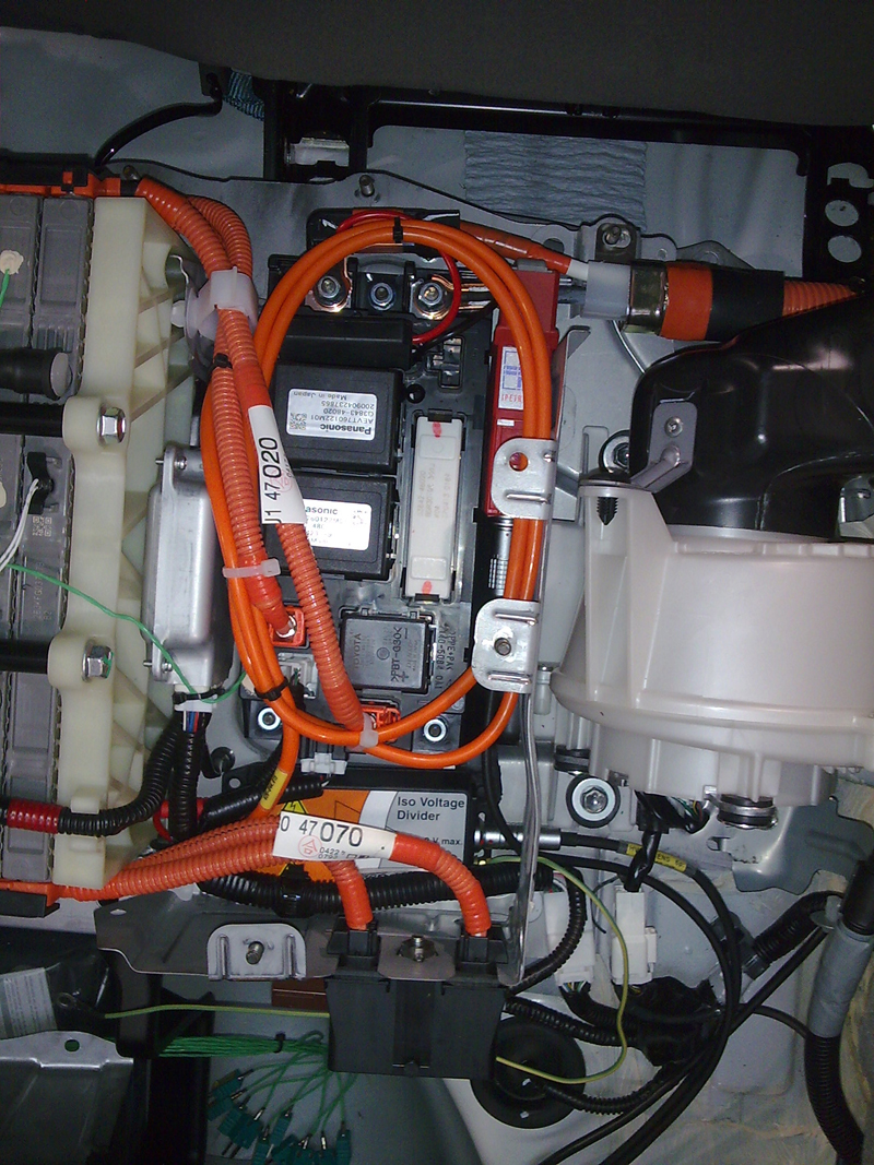
Figure 1: Typical positioning of high-voltage vehicle components
Recent industry trends toward high-performance electric and hybrid vehicle (EHV) drives has created a whole new set of testing requirements. New Drive Technologies, New Safety Requirements New systems call for onboard electrical energy stores and drive units with battery power requirements of up to 1000 Volts depending upon vehicle size and type. While such high-voltage systems are commonly known for their stationary use within power generation and energy distribution applications, they are still fairly unfamiliar to onboard EHV applications, though nonetheless are steadily increasing in popularity. It is important to understand that, if EHV drive construction was the same as traditional 12-, 24- or 42-Volt (nominal) on-board systems, units would create unreasonably high power requirements and end user costs, directly affecting a manufacturer's ability to produce cost-competitive new vehicles. Since power is a byproduct of both current and voltage, EHV on-board system voltage must increase to keep currents within "reasonable" limits. Such increased capabilities can diminish cable cross-sectioning requirements while fully optimizing drive system efficiency. To ensure optimal EHV performance, numerous tests must be conducted during the new vehicle development process. Suitable mobile vehicle data acquisition systems are vital for ensuring system competency, functionality and efficiency. In addition, proper incorporation of this technology as a viable onboard power source within an operating EHV requires a commitment to stringent safety testing and risk-mitigating hardware and accessories. Understanding a Typical High-Voltage Onboard System A typical high-voltage onboard system consists of two key components: the direct current grid (DC voltage) of the energy storage device; and the three-phase alternative current grid of the RPM-regulated drive (rotary current, 3~AC). An example of typical EHV high-voltage component positioning is shown below, as well as a typical block diagram of direct and alternating circuits found within these systems. Please note that universal safety precautions for AC and DC voltages must be followed at all times.
Common Measurement Parameters Electrical drive energy balance is a key EHV drive system measurement parameter, and particularly, studies of charge and discharge behavior and onboard energy storage device efficiencies, as well as high-voltage batteries and battery cooling systems, both single cell and total systems. Motor, generator and converter load behavior and drive component efficiencies may also be tested. Generally speaking, drive unit testing is typically conducted right on the test bench. A critical requirement is thus voltage and current detection within the direct current grid and if necessary, rotary current. Voltage data acquisition within this environment is conducted directly at the contact measurement point. System current data acquisition can be facilitated either via a shunt resistor to divide the conductor or via a current clamp. On-road EHV testing calls for considerably greater data acquisition and wiring challenges than stationary applications. Onboard or road test data collection within a typical test track environment subjects instrumentation to higher-than-usual shock and vibration inputs, placing greater mechanical demands upon components and systems. Onboard vehicle testing environments also tend to be more space constrained. Space limitations and associated added vibration friction risks can chafe improperly installed conductors. Wiring can also be damaged or severed, should it come into contact with sharp-edged vehicle parts. Cables can also be inadvertently crushed or sheared in test, affecting measurement integrity and compromising safety. Finally, risk of damage to components assembled after testing is considerably higher within onboard applications because they were simply not designed with high cross-sections or additional mechanical protection (e.g., protective tubing, wire mesh). If damage to an onboard high-voltage system goes undetected, undesirable consequences, ranging from loss of system functionality to serious personal injury, can result. Thus, use of a highly rugged data acquisition system that can be easily installed and wired within hard-to-reach areas of the vehicle is critical. Added Safety Considerations Direct current within EHV drive systems is outputted at much higher levels than typical alternating current. Prolonged exposure can cause thermal damage to the human body, including burns and cell tissue modifications. In addition, the practice of arcing when dividing direct current circuits with high inductivity requires special attention. IEC 61010-1 also sets forth instrumentation requirements for EHV testing. In addition, stringent safety guidelines are recommended by the European VDE Association for Electrical, Electronic & Information Technologies.
Understanding Risks A typical high-voltage on-board system design is similar to an IT network. In other words, the on-board system does not have a low ohmic connection to conductive parts, such as a vehicle body or chassis. To avoid risks of electrostatic discharge, both pins are high-ohmically connected to the vehicle mass via a RC-element. Connection security and safety should always be checked prior to working on the vehicle. As the schematic in figure 3 illustrates, a simple system insulation error (single connection to vehicle mass) poses no potential dangers, provided that no other simultaneous insulation errors occur. To ensure safety, any first insulation errors must be immediately detected and fixed. Within an EHV drive system, vehicle mass is at half-system voltage, or 500V and 250V, meaning that all onboard measurement devices, including data acquisition, absolutely require galvanically isolated insulation to avoid errors and risk of injury. In addition, suitable measuring cables must also be safely assembled and maintained. Common in-laboratory slotted lines are insufficient for this type of testing. All IPETRONIK high-voltage conductor wires are double insulated with true white core insulation beneath the black or red thin external insulation, allowing for easy detection of minor damages and cable replacement before a potential safety risk can occur. Another protective measure is use of a pre-scaler with the high-voltage cable. Hardware Requirements Stringent safety regulations dictate that only IEC category I thru IV measuring devices can be specified to support high-voltage EHV drive testing. The IPETRONIK TÜV-certified high-voltage Iso divider and four-channel high-voltage Iso data acquisition system are authorized for category I applications up to 1000 VDC and category II applications up to 600 VAC, allowing them to meet all high DC-voltage requirements to 1000V. When measuring with current clamps, the current clamp and subsequent measuring system (e.g. multimeter) must also correspond to the appropriate IEC category. The high-voltage Iso divider, compatible with any IPETRONIK measurement system or category I and II application can also be used to safely apply a high-voltage system current clamp. Another alternative is to use the high-voltage Iso data acquisition system, a compact four-channel system with direct CAN output, for safe and effective power balancing at the direct current area.
Converter Circuit Data Acquisitions EHV AC circuit data acquisitions between frequency converter and drive (motor/generator) are less frequently required, as key data is generally collected on the test bench. AC testing requires use of measuring devices which correspond at a minimum to IEC category III, as they must be able to safely handle surges up to 6000V at a nominal voltage of 600 VAC. IPETRONIK IPEmotion™ software includes a special hardware plug-in for power analyzers that configures and acquires data real-time, with online calculations of energy and power balance and user-defined signal scaling and acquisition rate settings. Acquired data can be evaluated with IPEmotion™ or directly converted into data formats and saved for further analyses. www.ipetronik.com


