System robustness through the rejection of system level noise
RS485 networks provide the backbone for communications in applications ranging from industrial control systems to roadside traffic message boards. In environments where high voltages are present, electrical isolation from the communication bus to logic controllers is regularly employed for human safety and equipment protection. Often overlooked, are the benefits of isolation affecting system performance rather than simply protecting it from dangerous voltages. These benefits come in the form of uninterrupted, error-free communication in the presence of harsh ground perturbations and other system level noise that would otherwise render a non-isolated system inoperative. Isolated RS485 transceivers are available from several manufacturers. Most of these solutions provide data isolation but do not provide the isolated power needed to drive the bus interface. The user is left to come up with the solution, requiring bulky, expensive discrete elements to make up the isolated DC/DC converter. The overall size, cost, power consumption, or complexity can deter the use of isolation in systems that could truly benefit from it. New Isolator mModule® technology from Linear Technology provides a complete power and data isolation solution in small LGA and BGA surface mount packages. The LTM2881 incorporates a robust isolated RS485 transceiver and an isolated DC-DC converter capable of delivering up to 1W of power for the bus interface circuits and auxiliary circuits. The μModule transceiver requires no external components - even the decoupling capacitors and an electrically switchable network termination resistor are built in.
RS485 was developed and standardized to allow communication between transceivers with ground potential differences of up to �7V. The signals on the bus can assume voltages of -7V to +12V with respect to the local "ground" at any node. These ground potential differences arise from a variety of conditions including earth ground variations or voltage drops on ground returns that are shared by other circuits under load. Under some circumstances extraneous transient events can produce ground shifts that far exceed �7V. These conditions will likely introduce errors in the received data, or worse yet, damage transceivers and their associated system circuitry. Proper use of an isolated transceiver, like the LTM2881, extends the usable common mode voltage (mean voltage of the differential signal lines with respect to ground) to �560V continuously or �3500VDC for 60 seconds. This level of isolation offers protection and uninterrupted communication from severe voltage disturbances such as indirect lightning strikes to networks spanning multiple buildings. Repetitive ground and signal disturbances can result from coupling to AC power lines routed adjacent to RS485 bus wires. Computers, printers, fluorescent lights, variable speed motor drives and other electronic non-linear loads can introduce significant frequency harmonics into power distribution neutral, ground lines, and communication network wires. These disturbances can cause real data errors in RS485 networks which isolation can alleviate.
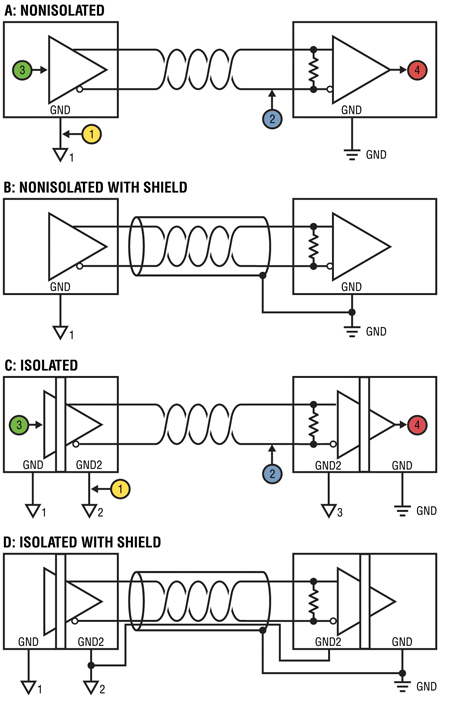
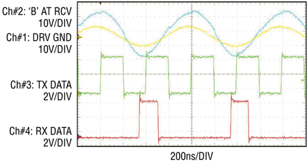
RS485 wiring configurations for non-isolated and isolated networks are shown in Figure 1. For simplicity, the illustration shows point-to-point unidirectional communication but the concept also applies to multi-node networks. Figure 1a shows a non-isolated, unshielded twisted pair connection implemented with Cat5e cabling. Figure 2 shows oscilloscope waveforms captured at points on this network while driving 100ft of cable and introducing a ground potential difference between driver and receiver. The trace colors correspond to the colors of the probe locations in Figure 1. All signals are measured with respect to earth ground at the output of the receiver. Channel 3 (green) shows the data signal into the transmitting driver at DI, while Channel 4 (red) is the data output from the remote transceiver's RO pin, which should follow the data input by only propagation delay. The yellow trace at the top of Figure 3 is the sine wave voltage signal introduced between grounds with 7V amplitude (14VPP). Channel 2 (blue), shows the "B" signal at the negative receiver input after it has traversed the 100' cable. The digital data at "B" is nearly imperceivable compared to the large common mode voltage signal it is superimposed on. Figure 2 shows obvious errors. There are two factors contributing to the loss of data, both relating to the finite common mode rejection capability of the RS485 receiver. First, the high frequency content of the common mode signal, here about 1.2MHz, exceeds the effective bandwidth of common mode rejection for most RS485 receivers. Secondly, the amplitude of the common mode signals presented to the receiver far exceeds the allowed range of -7V to +12V. In this case, the signal amplitude at the end of the 100ft wire has peaked up to �20V even though the stimulus introduced at the near end had voltage peaks of only �7V! This amplitude peaking is maximized at the resonant frequency of the network wiring. Note this does not refer to the differential characteristics of the bus, which behaves like a transmission line, but is a characteristic related to the common mode impedance. The resonant frequency is a function of the cable length, cable configuration (e.g., coiled or straight) and the complex impedance of the connected nodes. The interesting point is that a �7V common mode signal was able to corrupt RS485 signal transmissions due to the frequency content and amplitude peaking.
Replacing the RS485 transceivers with LTM2881 Isolated RS485 transceivers (Figure 1c) solves the problem of data corruption as is evident in the corresponding waveforms of Figure 3. In this configuration, the common mode applied to the receiver inputs is mostly developed across the isolation barrier. The receiver isolated ground moves with the common mode voltage of the receiver inputs, simply riding on top of it. As a result, the receiver does not see this as a common mode variation and continues to reliably detect the differential data. Notice that the common mode frequency has been increased to 2MHz, which causes the signal amplitude at the end of the cable into the receiver (blue trace) to increase significantly to 40VPP. This common mode voltage amplitude is far beyond the specification called out in the RS485 standard and would challenge most non-isolated RS485 transceivers.

Better choices for wiring include using shielded wire and a common wire that ties all isolated ground nodes together are discussed below. Figure 1b shows the non-isolated network connected using a shielded twisted pair, such as Belden 9841 cable. The shield should only be tied at one point to avoid creating ground loops. Connecting the shield to the receiver ground provides the best shunting for system performance. In multi-node, non-isolated networks the master node is typically the shield connection location. The shield serves to shunt coupled energy to ground rather than onto the signal wires and does not reduce the effects of ground differences between nodes. The best wiring option for use with isolated transceivers is illustrated in Figure 1d. All isolated grounds at each node are tied together with a common wire. The common connection is tied to non-isolated ground at one point to establish the nominal voltage reference level of the otherwise floating network. This prevents the bus from floating to excessive voltages beyond the isolation rating. This configuration elicits the best performance out of the RS485 receiver because the receiver's isolated ground potential follows the common mode of the input signals and is absorbed across the isolation barrier. Since the receiver ground moves with the signals, the receiver is not taxed with rejecting common mode voltage transients. Instead, the rejection happens at the isolation boundary where the LTM2881 encodes the data into differential digital pulses before inductively coupling it across the barrier. This communication method is tolerant of extremely high common mode transient events faster than 30kV/μs with no data loss or added jitter. Figure 1d also shows a separate shield tied at one point to earth ground to shunt coupled noise. However, some systems will not have both a shield and separate reference wiring options. In this case, the best option is to tie the shield to the common terminal of each isolated transceiver and then to earth ground at one location. If RF immunity remains a concern, a high frequency, high voltage, capacitor from each receiver common to ground can help shunt the energy away from the transceiver.

Figure 4 shows a typical usage of the LTM2881 isolated RS485 transceivers arranged in a half-duplex network with their isolated common nodes (GND2) wired together for optimal performance as discussed.
Isolation improves system robustness through the rejection of system level noise. Products like Linear Technology's LTM2881 isolated RS485 mModule transceiver with integrated isolated power, make it easier than ever to get the best performance out of a communication system. www.linear.com


