Author:
Giusy Gambino and Roberto Caputo, STMicroelectronics
Date
11/20/2025
 PDF
PDF

Click image to enlarge
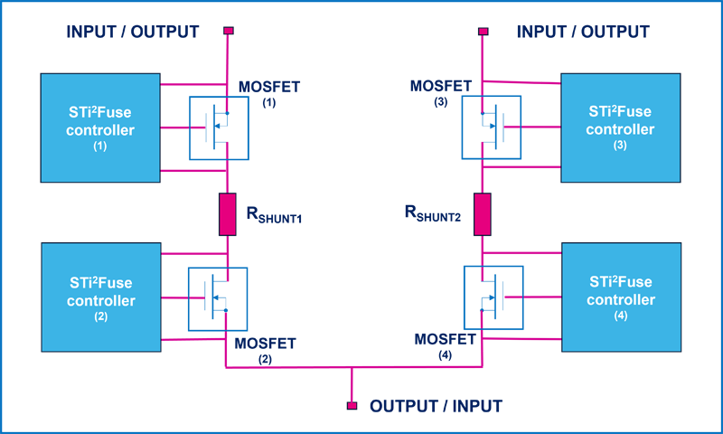
Figure 1: Schematic configuration of a controlled bidirectional line
The automotive industry is experiencing a paradigm shift fueled by the rapid adoption of electrification, advanced driver assistance systems (ADAS), and the progression toward autonomous and connected vehicles. These innovations demand increasingly complex and reliable electrical systems capable of handling higher power levels while maintaining safety and efficiency.
Traditional centralized power distribution architectures, which rely on extensive wiring harnesses and centralized control units, are becoming less feasible due to their complexity, weight, and limited scalability.
To address these challenges, the industry is transitioning toward zonal electrical architectures. In this approach, the vehicle’s electrical system is divided into several manageable zones, each responsible for powering specific subsystems or areas of the vehicle.
This segmentation reduces wiring complexity, lowers weight, improves maintainability, and enhances fault isolation capabilities. However, zonal architectures require innovative power distribution components capable of flexible, safe, and efficient operation under stringent automotive standards.
Power Rail Switch in Zonal Architectures
A key element in zonal architectures is the Power Rail Switch (PRS), which acts as a controllable node for power distribution across multiple load lines. The PRS must support a bidirectional current flow to accommodate dynamic power routing and fault management scenarios. It also needs to provide robust protection mechanisms to quickly isolate faults and maintain overall system stability.
STMicroelectronics’ STi²Fuse smart fuses are designed to meet these challenging requirements. They integrate advanced hardware and software features to enable precise control, real-time diagnostics, and fast fault response.
The PRS solution described here leverages four STi²Fuse devices configured back-to-back (B2B) to form bidirectional power switches capable of handling two different paths with a current up to 150A at 48V.
This B2B MOSFET configuration provides symmetrical voltage blocking in the OFF state and supports bidirectional current flow when ON, effectively replicating the behavior of an ideal bidirectional power switch (BPS).
Bidirectional Power Switch (BPS) Concept
The BPS is an active switch that can conduct current in both directions when turned ON and block it in both directions when OFF. In the ideal representation of a BPS, the two lines, named Line L and Line R, are interchangeable input and output terminals.
The back-to-back (B2B) configuration for two N-channel MOSFETs with common drains can be used to create a BPS. This configuration provides symmetrical OFF state blocking characteristics similar to the BPS. By controlling the gates G1 and G2 with a driver circuit, it is possible to create a controlled bidirectional line, as depicted in Figure 1:
The gate drivers ensure precise switching and protection control, making the B2B configuration ideal for automotive power distribution applications.
Power Rail Switch (PRS) Implementation
This configuration of the PRS was implemented by using two bidirectional lines connected in common node and driving the MOSFET gates with the STi2Fuse controller VNF1248F, as shown in Figure 2.
Click image to enlarge
Figure 2: Schematic configuration of the power rail switch
The four VNF1248F devices manage the gate signals and protection mechanisms to ensure safe operation under fault conditions, including:
· Overcurrent (OVC) and Hard Short-Circuit (HSC) protection to detect abnormal current events.
· Current vs time latch-off protection for fuse function emulation, fully configurable via SPI (Serial Peripheral Interface).
· Thermal management to activate external MOSFET overtemperature shutdown.
Experimental Results
The measurements were conducted using a hardware setup composed of three stacked layers:
· A microcontroller board programmed with specific firmware.
· A driver board equipped with the Sti2Fuse controllers.
· A power board containing the MOSFETs.
A graphical user interface (GUI) was employed to program the four VNF1248F controllers and provide real-time diagnostic feedback.
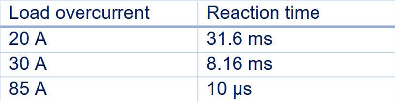
When a short circuit occurs on both rail lines, the VNF1248F devices act to protect the load. The reaction time of these devices decreases as the overcurrent level increases, with response times governed by the I²t curve configured within the smart fuses.
The experimental data are summarized in Table 1.
Click image to enlarge
Table 1: Experimental data for smart fuses reaction times
The I²t protection tests demonstrate reaction times as low as 10 microseconds for high current faults (up to 85A), confirming the PRS’s capability to rapidly disconnect faulty lines while maintaining overall system stability.
In the event of a short circuit on only one rail line (L2), the VNF1248F devices isolate the faulty rail, protecting the load. The load’s functionality is preserved by the other healthy rail line (L1), as illustrated in Figure 3.
Click image to enlarge
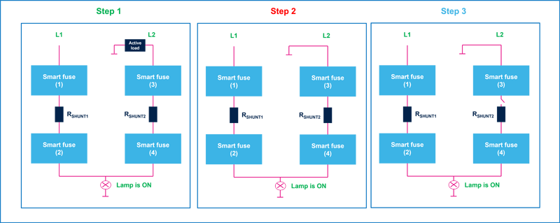
Figure 3: Hard short circuit event on rail line (L2)
The test sequence is divided into three steps:
Step 1: Normal operation
· Both L1 and L2 rails are operating normally.
· The lamp connected to the circuit is ON, indicating that power is flowing correctly.
· Both smart fuses 1 and 3 have their gates active, allowing current flow.
Step 2: Hard short circuit occurs on L2
· L2 is suddenly shorted to ground (hard short).
· Smart fuse 3 detects the fault and latches, forcing its gate to LOW to block current flow and protect the circuit.
Step 3: Fault isolation
· L2 is opened (disconnected) by smart fuse 3, effectively isolating the short circuit.
· The other parts of the system remain protected and operational.
· The lamp is still ON, powered by the healthy rail (L1), demonstrating the system’s fault tolerance and selective protection.
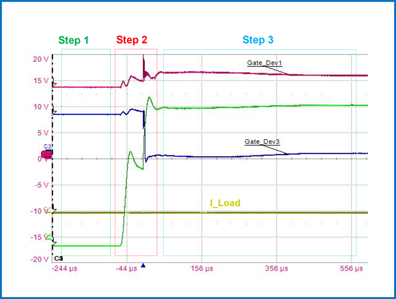
The measured voltage and current waveforms during the hard short circuit event on L2 are shown in Figure 4.
Click image to enlarge
Figure 4: Measured waveforms during the hard short circuit event on the L2 line
Despite the fault on L2, the voltage and current on the healthy rail (L1) remain stable, ensuring continuous power delivery to the load (lamp remains ON). This demonstrates the effectiveness of the bidirectional power switch and smart fuse configuration in maintaining system operation and protecting against faults.
Conclusions
An innovative power distribution solution for automotive zonal architectures is presented, leveraging STMicroelectronics’ STi²Fuse smart fuses combined with a back-to-back MOSFET configuration to implement a bidirectional Power Rail Switch (PRS). The PRS provides flexible and secure power distribution, featuring symmetrical voltage blocking and bidirectional current flow capabilities.
Experimental results demonstrate rapid fault detection and isolation times as low as 10 microseconds, ensuring robust load protection and system stability. This solution effectively meets the evolving demands of modern automotive electrical systems, delivering enhanced reliability, scalability, and safety for next-generation zonal architectures.