Author:
James Scanlon and Conal Watterson, Analog Devices
Date
01/12/2014
 PDF
PDF
Industrial and instrumentation applications (I&I) require transmission of data between multiple systems often over very long distances. The RS-485 bus standard is one of the most widely used physical layer bus designs in I&I applications. Applications for RS-485 include process control networks, industrial automation, remote terminals and building automation, such as heating, ventilation, air conditioning (HVAC), security systems, motor control and motion control.
In these real systems, lightning strikes, power source fluctuations, inductive switching and electrostatic discharge can cause damage to communications ports by generating large transient voltages. Designers must ensure that equipment does not just work in ideal conditions but also work in the ‘real world’.
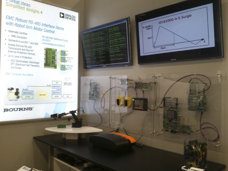
The robustness of our solution for RS-485 networks is demonstrated in an example network with robotic arm control and real surge pulses applied directly to the communication lines using an electric fence energizer.
The Demonstration Network
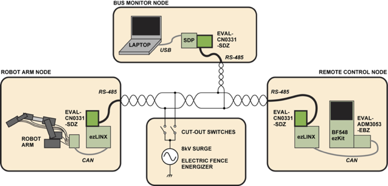
The EMC-protected RS-485 circuit, the EVAL-CN0313-SDP design tool, is demonstrated on a motor control network comprising of three nodes: a robot arm control node, a remote control routine node, and a third node to monitor the bus data from a PC. The robot arm node controls servomotors in the arm via PWM outputs from ADuC7128 microcontrollers, which responds to control messages received via CAN from an ezLINX board translating to/from the RS-485 data via UART to the RS-485 EMC board. The remote control routine includes a BF548 ezKit allowing touch-screen selection and playback of routines, again with a CAN interface and ezLINX board for translation to and from RS-485. The PC node consists of a system demonstration platform board to interface with the PC software over USB as well as a UART interface to the RS-485 EMC board. Figure 1 shows a block diagram of the three node network with the electric fence energizer.
Click image to enlarge
Figure 1. RS485 Three Node Network with Electric Fence Energizer Block Diagram
The A and B lines of the communication bus are subjected to direct injection of an 8kV transient from an electric fence energizer (waveform shown in Figure 2). This equipment is designed to electrify 60 km of fencing (e.g. keeping livestock in a field). As the demonstration has bare PCBs in a Perspex display, with no earthed chassis for the PCB grounds to connect to, the earthed cable shield is connected to the PCB grounds to provide the most direct ground return. Cutout switches (seen in yellow in the center of the photo in Figure 3) provide a high-voltage resilient mechanical switch to disconnect the fence energizer between demonstrations. This allows the energizer to build up enough charge for the full 8kV discharge in the next demonstration.

Click image to enlarge
Figure 2. 8 KV Transient from the Electric Fence Energizer
Click image to enlarge
Figure 3. RS485 Three Node Network with Electric Fence Energizer Block Demonstration
When transients are coupled in, the action of the gas discharge tubes (GDTs) can be directly observed, as they light up with each discharge, co-incident with the audible clicking of the fence energizer action. These GDTs shunt the main power of the transients to the ground, but only do so after the faster response of the transient voltage suppressor (TVS) and totally integrated surge protector (TISP) devices, such that all three types of protection component act together to protect the ADM3485 RS-485 transceiver.
Electromagnetic Compatibility
To ensure that these designs can survive in the ‘real world,’ various government agencies and regulatory bodies have imposed EMC regulations. Compliance with these regulations gives the end user assurance that designs will operate as desired in electrically harsh environments.
The IEC61000 specifications define the set of EMC immunity requirements that apply to electrical and electronic equipment intended for use in residential, commercial and light industrial environments. This set of specifications includes three types of high voltage transients that designers need to be concerned about for the data communication lines:
• IEC 61000-4-2 Electrostatic Discharge (ESD)
• IEC 61000-4-4 Electrical Fast Transients (EFT)
• IEC 61000-4-5 Surge Immunity
Each of these specifications defines a test method to assess the immunity of the equipment against the defined phenomenon. It’s important to note that the ESD and a single EFT pulse have similar waveform characteristics giving them similar energy levels. The surge pulse, however, has energy levels three to four magnitudes higher than the ESD and EFT pulse, making it the most destructive of the three. Due to the similarities between ESD and EFT, the design of the circuit protection can be similar; however, due to its high energy, surge must be dealt with differently. This is one of the main issues in developing protection circuitry that improves the immunity of data ports to all three transients while remaining cost effective.
EMC Protected RS485 Circuit or RS485 Transient Suppression Networks
By nature, EMC transient events vary in time, so the dynamic performance and the matching of the dynamic characteristics of the protection components with the input/output stage of the protected device leads to successful EMC design. Component datasheets generally only contain dc data, which is of limited value given that the dynamic breakdowns and I/V characteristics can be quite different from the dc values. Careful design, characterization and an understanding of the dynamic performance of the input/output stage of the protected device and the protection components is required to ensure that the circuit meets EMC standards.
Analog Devices (ADI) and Bourns have collaborated to extend their offering of system-oriented solutions by developing what is believed to be the industry’s first EMC compliant RS-485 interface design tool that provides up to Level 4 protection for IEC61000-4-2 ESD, IEC61000-4-4 EFT and IEC61000-4-5 surge. It gives engineers the design options depending on the level of protection required and available budgets. These design tools allow engineers to reduce risk of project slippage due to EMC problems by considering them at the start of the design cycle.
The circuits shown in Figure 4 illustrate three different fully characterized EMC compliant solutions. Each solution was certified by an independent external EMC compliance test house, and each provides different cost and protection levels for ADI’s ADM3485E 3.3 V RS-485 transceiver with enhanced ESD protection using a selection of Bourns’ external circuit protection components. The Bourns’ external circuit protection components used consist of transient voltage suppressors (CDSOT23-SM712), transient blocking unit (TBU-CA065-200-WH), thyristor surge protectors (TISP4240M3BJR-S) and gas discharge tubes (2038-15-SM-RPLF).

Click image to enlarge
Figure 4. Three EMC Compliant ADM3485E circuits (Simplified Schematic, All connections not shown)
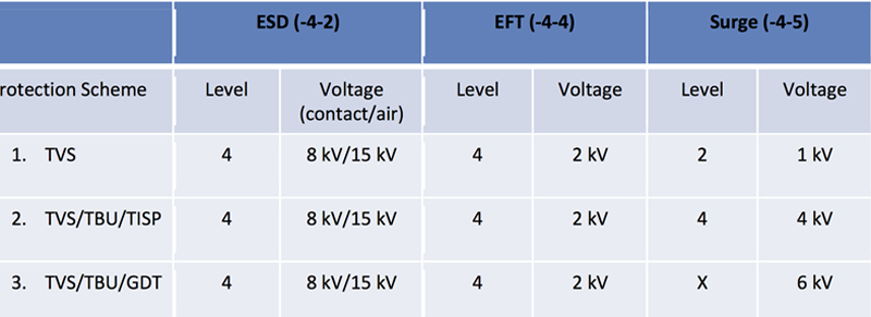
Each solution was characterized to ensure the dynamic I/V performance of the protection components defend the dynamic I/V characteristics of the ADM3485E RS-485 bus pins. It is the interaction between the input/output stage of the ADM3485E and the external protection components that function together to protect against the transient events. The levels of protection offered by the three different circuits are shown in Table 1.
Click image to enlarge
Table 1. Three ADM3485E EMC Compliant Solutions
Conclusion
RS-485 interfaces can be effectively protected from real world high voltage transients using the solution provided by the EVAL-CN0313-SDPZ. Subjecting a robot control network to the charge from an electric fence energizer provides a robust demonstration of the board’s capabilities. The key challenge in designing EMC compliant solutions for RS-485 networks is matching the dynamic performance of the external protection components with the dynamic performance of the input/output structure of the RS-485 device. Three different EMC compliant solutions for RS-485 communication ports were presented in this article, giving the designer options depending on the level of protection required. The EVAL-CN0313-SDPZ is industry’s first EMC Compliant RS-485 customer design tool providing up to and including Level 4 protection levels for ESD, EFT and Surge. While these design tools do not replace the due diligence or qualification required at the system level, they allow the designer to reduce risk of project slippage due to EMC problems at the start of the design cycle, hence reducing design time and time to market. For more information please visit: www.analog.com/RS485emc.