Supercapacitors are increasing in popularity amongst board-level components. In turn, there is now greater demand for supercapacitor reliability testing data, as sub-ppm component failure rates are critical for minimizing and eliminating PCB rework.
The following case study addresses basic supercapacitor reliability testing and application guidelines, and then delves into test conditions and long-term reliability test data for AVX’s SCM and SCC Series supercapacitors tested at 85°C and at various applied voltages — both at and below rated voltage — for more than 4,000 hours to demonstrate the impact of voltage on supercapacitor reliability, reveal performance characteristics that are currently unique to this series, and boost overall confidence in supercapacitor reliability.
Supercapacitor Reliability Testing Guidelines
Extensive testing is required to achieve a comprehensive understanding of an electronic component’s device physics, degradation behavior, and failure mechanisms, and to accurately establish its long-term reliability. Such detailed part characteristics and performance data also help engineers recommend optimal, application-specific component solutions based on operating conditions, including voltage, temperature, relative humidity, and equivalent series resistance (ESR).
Electrochemical devices, like supercapacitors and batteries, are not well suited to typical electrostatic capacitor testing techniques, which use higher voltages and temperatures as acceleration factors. One of the primary requirements for the effective use of voltage and temperature acceleration is that their corresponding mechanisms should stay the same, and that is not the case for electrochemical devices. Using higher voltages and temperatures than a supercapacitor is rated for will cause hastened degradation of capacitance and a significant rise in ESR, so these conditions are not representative of normal operating conditions.
Due to these limitations, supercapacitors should only be tested at or below the maximum rated voltage and temperature, but for a longer span of time than electrostatic capacitors. It is also possible to test these devices at or below the rated voltage and temperature, ensure that the mechanisms do not change, and then use that data to estimate the failure rates over time; however, verifiable, long-term testing is preferable whenever possible.
Supercapacitor Application Guidelines
Supercapacitor lifetimes are a function of both voltage and temperature. So, operating conditions in excess of their rated voltage and outside of their rated temperature range can cause accelerated supercapacitor failures and can permanently damage entire circuits. As such, it is critical to define an application’s operating conditions before attempting to specify or estimate the lifetime of a supercapacitor.
The rated voltages of standalone supercapacitors are generally lower than other energy storage devices, like batteries, so supercapacitors are often placed in series to attain desired voltage values. However, using capacitors in series tends to create a voltage imbalance during the charge and discharge cycle, which can threaten the maintenance of operation at or below rated voltage and negatively affect the longevity of all components in the circuit. There are several circuit balancing techniques that can effectively surmount this issue (e.g., passive balancing with a resistor across a capacitor or with a diode, active balancing with an IC chip, using a buck-boost converter with a single large capacitor to scale up the voltage, etc.), but each requires the addition of nonessential components that could infringe upon space-constrained device footprints, negatively affect load current, and create yet another potential point of failure.
Test Conditions
The following case study provides extensive, 4,000-hour reliability test dataabout thelifetime characteristics of supercapacitors. Itinvestigates both capacitance and ESR over time under several different test voltages and temperatures varied to simulate harsh-environment operating conditions, such as high and low temperatures and relative humidity.
It also employs some general rules of thumb established through 12 years of electrochemical device testing experience and verified by crosschecking the results for validation. For instance, failure rate (F) has been shown to follow the relationship:
in which “V" is voltage, “n” is the voltage exponent, “Q” is the activation energy (measured in electronvolts [eV]), and “k” is the Boltzmann constant.
SCM Series Long-Term Reliability Test Results
The following test procedures were conducted on AVX’s SCM Series supercapacitor modules, which, unlike other supercapacitors in series, do not require balancing circuitry. Introduced to market in October 2016, SCM Series supercapacitor modules are comprised of SCC Series cylindrical, electrochemical, double-layer supercapacitors connected in series and produced using a core-matching technique that combines capacitors with similar capacitance, ESR, and leakage current values (assuming that leakage current values were measured when the charging current reached an asymptotic value, i.e., after approximately 72 hours of test time).
Backed by over 4,000 hours of data, this technique imbues the series with exhibit optimal hold-up, energy harvesting, and pulse-power handling characteristics, including: very high capacitance (0.47–7.5F ±20% tolerance), extremely low ESR, (4–300mΩ at 1KHz), low leakage (2–1,000µA), and high energy density (1–5.6Wh/kg), and long-lifetime performance (500,000+ cycles), and is responsible for its unique ability to operate effectively without balancing circuitry.
SCM Series parts rated for 5V/5F (SCMT22C505MRBA0) were tested at various applied voltages at 85°C, and the results clearly demonstrate that the parts exhibit a decreasing rate of change in capacitance as the voltage drops and that ESR values become stable with time.
At rated voltage, all SCM Series parts are rated for a maximum operating temperature of 65°C. So, the part under test suffered catastrophic failure at rated voltage and 85°C (Figure 1), which verifies the critical nature of operating supercapacitors within their rated voltage and temperature range.

Click image to enlarge
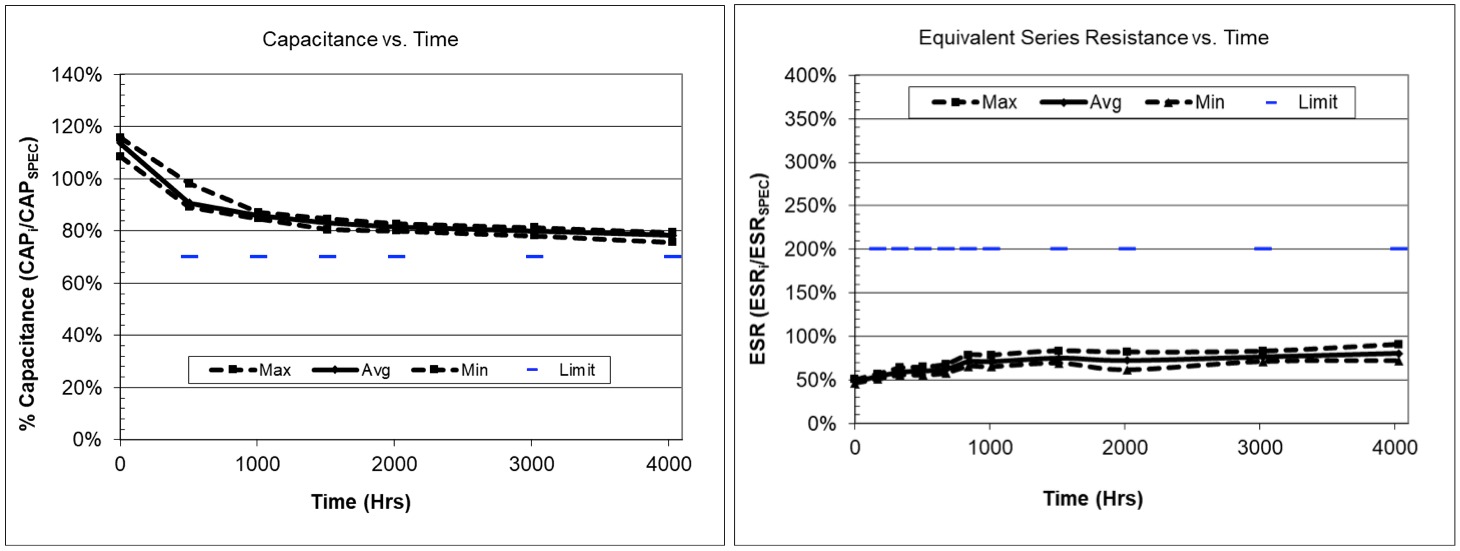
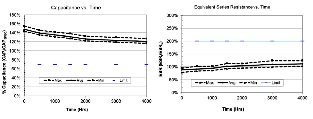
Figure 2. This graph pair represents Capacitance vs. Time and ESR vs. Time for the SCMT22C505MRBA0 at 90% rated voltage (4.5V) for 4,000 hours at 85°C.
Derating to 90% (4.5V) of rated voltage drastically improved the longevity of the part (Figure 2). In this test, the 5F part lost 30% of capacitance after a little more than 3,000 hours, and ESR began exhibiting a slow rise at the same mark. As such, it can be safely concluded that this part would survive 85°C operating temperature for 3,000 hours at 4.5V operating voltage.
Click image to enlarge
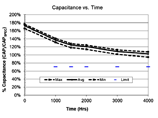
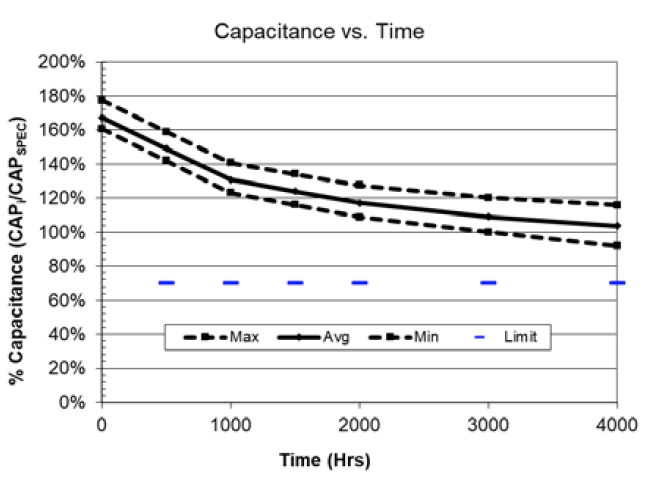
Figure 3. This graph pair represents Capacitance vs. Time and ESR vs. Time for the SCMT22C505MRBA0 at 80% rated voltage (4.0V) for 4,000 hours at 85°C.
At 80% of rated voltage (4.0V), the part almost passed 85°C testing conditions for 4,000 hours. The ESR curve was encouraging — demonstrating a slow, lethargic rise — however, the capacitance dropped off after 3,000 hours of testing (Figure 3).
Click image to enlarge
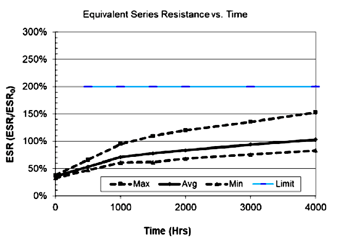
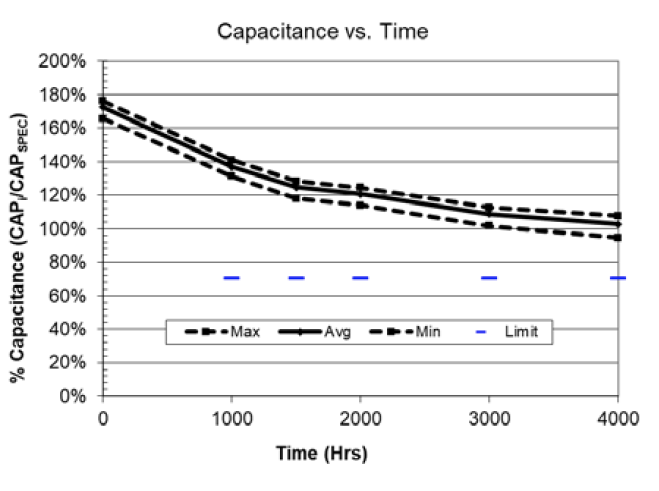
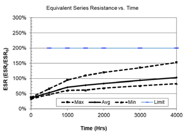
Figure 4. This graph pair represents Capacitance vs. Time and ESR vs. Time for the SCMT22C505MRBA0 at 70% rated voltage (3.5V) for 4,000 hours at 85°C.
At 70% of rated voltage (3.5V), capacitance reached an asymptotic curve and ESR remained stagnant (Figure 4). The 5V/5F SCM Series part (SCMT22C505MRBA0) easily passed 4,000 hours of testing at 85°C operating temperature.
The curve in a Capacitance vs. Time plot of an unbalanced 5V/0.47F module tested at rated voltage and 70°C for 4,000 hours (Figure 5) also illustrates that capacitance reached an asymptotic value, which indicates slow degradation of capacitance.

Click image to enlarge
Figure 5. This graph represents Capacitance vs. Time for the 5V/0.47F SCMR14C474MRBA0 at rated voltage for 4,000 hours at 70°C.
Similarly, when an unbalanced, 5V/1F, two-capacitor module (SCMR18C105MRBA0) was tested at rated voltage, 40°C, and 95% relative humidity for 4,000 hours, it easily passed both Capacitance vs. Time and ESR vs. Time tests, proving its suitable under said conditions (Figure 6).
Click image to enlarge
Figure 6. This graph pair represents an unbalanced, 5V/1F SCMR18C105MRBA0 at rated voltage (5V), 40°C, and 95% relative humidity for 4,000 hours.
SCC Series Long-Term Reliability Test Results
The following test procedures were conducted on AVX’s SCC Series cylindrical, electrochemical, double-layer supercapacitors — the building blocks for the SCM Series modules. Produced using the same core-matching techniques as described above, the SCC Series currently offers the industry’s smallest 2.7V/1F supercapacitor (SCCR12B105SRB)and also exhibits optimal hold-up, energy harvesting, and pulse-power handling characteristics, including: very high capacitance (1–3,000F), extremely low ESR (0.16–200mΩ at 1KHz), low leakage (6–5,800µA), high energy density (1.2–5.6Wh/kg), and long-lifetime performance (500,000+ cycles).
At rated voltage, all SCC Series parts are rated for a maximum operating temperature of 65°C. Long-term testing of a2.7V/1F (SCCR12B105SRB) part at 70°C and a derated voltage of 2.1V demonstrated that capacitance reached an asymptotic value as testing neared the 4,000-hour mark (Figure 7).
Click image to enlarge
Figure 7. This graph represents Capacitance vs. Time for the 2.7V/1F SCCR12B105SRB at roughly 77% rated voltage (2.1V) for 4,000 hours at 70°C.
When the same part number was tested with rated voltage applied and held at 70°C for 4,000 hours, capacitance easily withstood the test conditions (Figure 8).
Click image to enlarge
Figure 8. This graph represents Capacitance vs. Time for the 2.7V/1F SCCR12B105SRB at rated voltage (2.7V) for 4,000 hours at 70°C.
When, similar to the SCM Series test depicted in Figure 4, a 2.7V/10F (SCCS30B106SRB) part was tested at 70% of rated voltage (1.9V) and held at 85°C, it also easily passed performance requirements regarding ESR over time (Figure 9).
Click image to enlarge
Figure 9. This graph represents ESR vs. Time for the 2.7V/10F SCCS30B106SRB at 70% rated voltage (1.9V) for 4,000 hours at 85°C.
Conclusions and Implications
The results of this case study clearly indicate that AVX’s SCM and SCC Series supercapacitors operate well within rated specifications at elevated temperatures and exhibit unique qualities that enables their use at ≤4V and 85°C. These proven performance capabilities are important because they provide long-term evidence of the technology’s suitability for use in parallel with lithium ion (Li-ion) batteries — a feature that is not currently offered by any other supplier in the industry.
When derated to typical operating temperatures spanning 25°C to 45°C, long-term reliability testing data indicates that these parts are expected to last more than 20 years. As such, testing supports that these unique supercapacitors offer ideal solutions for hold-up, energy harvesting, and pulse-power circuits in industrial and consumer applications including: smartphones, uninterrupted power supplies (UPS), wireless alarms, remote meters, global systems mobile (GSM) and general pocket radio service (GPRS) transmissions, camera flash systems, scanners, drones, toys, and games.


