Understanding and Overcoming the Challenge of Powering AI in Data Centers

How to enable reliable, efficient, and scalable power architectures for next-gen data centers using right-fit AI-specific power solutions
Figure 1: 4:1 Zero-voltage switching (ZVS) switched capacitor (ZSC) topology
Introduction
Today’s data centers typically contain a dual-CPU server connected to multiple hard drives. These server systems excel at storing large amounts of information while processing a limited amount of it. However, they are not optimized for number crunching the huge volumes of data that help keep us safe from hackers, answer questions about the universe, or even drive an automobile.
For these hugely compute-intensive tasks, artificial intelligence (AI) and machine learning processors are required. AI chips work differently from a CPU which is typically designed to manage any number of general tasks, and as a result, it is not a specialist in anything. On the other hand, an AI processor is designed to do just one thing – number crunch large data sets. It excels in doing a few things but does each of them exceptionally fast. It can also be easily segmented into smaller processor blocks so that many smaller processors in parallel can be designed into a single large ASIC.
The result is massive AI ASICs with more than 50 billion transistors, all requiring one thing in common – power. As AI systems make their way into massive data centers, the density and power challenges are as intense as the computational performance of these systems.
In this article, we explore the challenges of powering AI in the data center, from the density challenge of squeezing more hardware into smaller systems to finding ways to deliver ever more current through smaller wires. We then consider how Infineon responds to these challenges through its ongoing development of energy-efficient AI-specific power solutions for data centers.
Power delivery
Traditionally in data centers, power for servers is drawn from an AC wall outlet, which is then converted to 12 V DC using a “silver box” power supply. This 12 V DC is then regulated down to approximately 1 V to power processor ICs. 12 V was chosen because it allowed for battery backup in the event of power failure. However, while this has worked well for decades, it requires closer examination when applied to data centers, where there are several approaches for power delivery.
One option is to distribute AC to each server, but this would require a ‘silver box’ and battery on each server. Distributing DC directly to each server leads to a rack (or multi-rack) power distribution scheme with a centralized AC-DC converter and a centralized battery bank. While this can yield operational efficiencies, as the number of servers on each centralized power source increases, so does the current on the 12 V bus, which makes distribution challenging as currents reach the hundreds or low thousand-amp range. Increasing the distribution voltage to a higher voltage can reduce these currents significantly and the accompanying power losses.
Transitioning to 48 V
While 48 volts would logically appear to be the next highest voltage to use, the transition to using it in data centers has been slow. However, AI brings a different set of challenges, with processors now being designed as nodes on self-contained modules so that processing performance can be significantly scaled up. If individual processors are interconnected, the more interconnects and the higher data bandwidth each processor supports leads to better performance.
The connectors that convey all these signals in a module or subassembly must have robust signal integrity, which can be provided by using dedicated pins. However, this limits the number of pins left over for power. A 48 V pin provides four times the power delivery of a 12 V pin, so migrating to a higher bus voltage makes sense for AI. The OAM form factor (the standardized AI modular solution presented by the open compute project) defines a power limit of 350 W (if a 12-volt bus voltage is used) but a more generous 750 W for 48 volts.
Increasing the bus voltage reduces power loss, but the choice of which voltage to use is not clearly defined. While 48 V is well known, in some computing systems, 54 volts is used, and during a power failure, this can even reach 60 V. If the output of the bus converter is another DC-DC buck converter regulated to a fixed voltage, then a slight change in input voltage is not a major problem. However, for other components like fans, hard drives, or expansion slots, a fixed 12-volt supply is required – hence, a regulated intermediate bus converter is needed. For that reason, Infineon has developed intermediate bus converter solutions suitable for data centers using a 48 V power distribution with both regulated and unregulated versions.
Intermediate Bus Converter solutions
The first of the three topologies is a variation of the Switched Tank Capacitor (STC) converter. It realizes a resonant tank circuit using a parasitic inductor. An additional inductor enables Zero-Voltage Switching (ZVS) for all the MOSFETs regardless of current load level, named Zero voltage switching Switched capacitor converter (ZSC). This allows for a much smaller circuit with no inductor saturation limit. It is 99 percent efficient and provides a full load power capability of over one kW at 48 V (see Figure 1).
The second solution is a Dual-stage Regulated Switched Capacitor (DR-HSC) converter which addresses the need for a regulated 12 V supply where the input voltage is between 40 V to 60 V. DR-HSC is a cascaded two-stage approach (see Figure 2a). The first stage comprises a ZSC 2:1, and the second stage is formed by two multi-level half-bridges. The phase nodes of the half-bridges are shorted to a common inductor and controlled in such a way to be phase shifted by 180° to achieve natural flying capacitors balanced (see Figure 2b).
Click image to enlarge
Figure 2a: Regulated 12 V bus converter

Click image to enlarge
Figure 2b: Regulated 12 V bus converter
In this case, it is interesting to analyze the DP-3LFC behavior for different duty cycles. A particular case is at 50 percent duty cycle. In this operation mode, the output inductor ripple is almost zero enabling the use of VRM inductors value. The overall efficiency is 98.5 percent for this approach, which has the added flexibility of separating the two intermediate stages to better utilize existing board layouts more efficiently for AI.
A third option uses a hybrid switched-capacitor (HSC) converter. HSC combines the benefits of switched capacitor converters and the high step-down ratio capability of a magnetic device. By transferring the energy through capacitors and a magnetic device, the efficiency and power density can be improved significantly at a high ratio, achieving above 98 percent efficiency.
These module designs allow for flexible placement on the system board without interference from high-speed PCB routing.
Second stage advances
As power levels increase, AI processors require lower input voltages (below 1 V DC). The amount of current required in the second stage of a converter also increases.
Common solutions have included paralleling buck DC-DC stages to make multi-phase converters. These increase power in multiples, improve transient performance, and reduce output ripple but use more space. Infineon’s latest power stages can provide up to 90 amps per phase, with their digital controllers now supporting up to 16 phases. However, while these can provide the level of DC current required, they are only suitable for use in environments with room for large inductors and sufficient cooling.
Unfortunately, AI provides neither luxury with constraints on component height, reducing the allowable current per phase, thus resulting in an ever-increasing phase count. Some AI cards are now approaching 30 phases of multi-phase regulation, and while this may seem extreme, it is essential to be aware that most AI processors use several input voltages. While the main rail carries the highest current, several additional rails can also carry more than a hundred amps. These multi-phase regulation schemes provide flexibility to address all the power rail requirements for today’s high-performance AI processors.
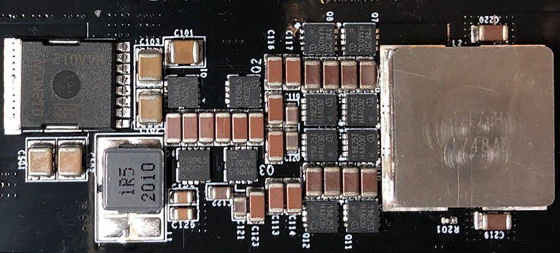
Infineon’s latest power stages meet the efficiency and thermal requirements for implementing AI in data centers. The AI evaluation board shown has 12 power stages placed between the mounting holes specified by the OAM (both north and south). This is possible by using new 4×6 mm2 power stages instead of the standard 5×6 mm2 packages. This allows two extra phases on each side (four in total), supplying an additional 200 amps of power. Given the power limits for AI processors in the OAM form factor, each additional percentage of efficiency gained makes more power available to the processor and reduces the heat that must be removed from the power supply. Here, the efficiency is almost 95 percent at 1.8 V.
To ensure the highest system performance, Infineon has also developed a new series of digital multi-phase controllers to meet the increasing demands for high-quality power. A seventh-generation digital controller features current mode control in a variety of packages supporting eight, 12, and even up to 16 phases per controller. It maintains full flexibility over the dual loop design and enables 2 MHz switching frequencies (or higher).
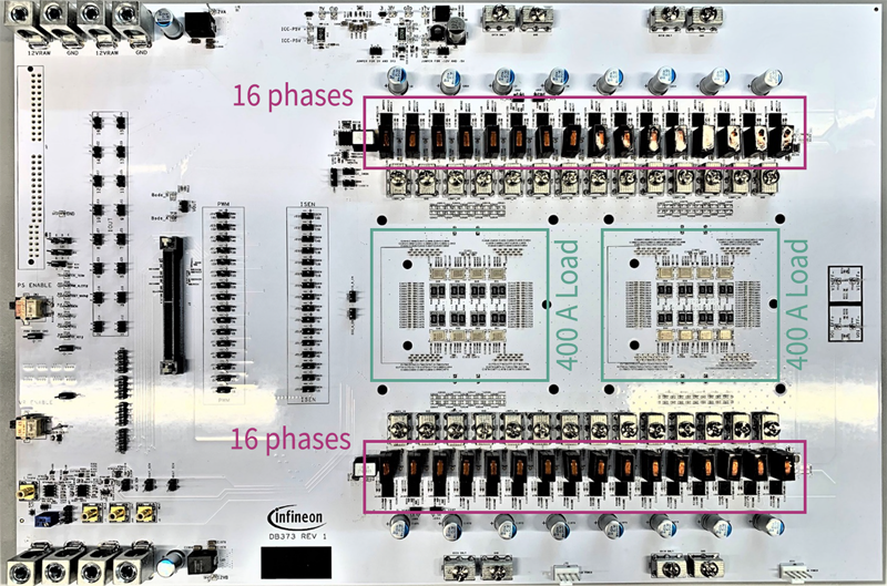
The XDP™ digital controllers incorporate a high-performance dedicated analog front-end and use state machine control of closed-loop regulation. External interfaces are managed by an integrated ARM® Cortex®-M0 microcontroller, allowing firmware-based upgrades of communication protocols, new feature requests, or even last-minute specification changes without the requirement for repeated silicon spins. More specifically, the XDPE controller has been designed to serve as a platform for a series of next-generation controllers, allowing for a more streamlined IC development process over a variety of product platforms, starting with the reduced latency and fast ADC for a rapid response to changing system conditions. Infineon’s XDP™ XDPE 152 series hyper transient phase controllers (XDPE15284D, XDPE15254D, XDPE152C4D) now also support Trans Inductor Voltage Regulation (TLVR) [1], with the 32-phase board shown supplying two electronic loads (see Figure 3).
Click image to enlarge
Figure 3: Advanced XDPE digital controller with TLVR support
Conclusion
Data centers are the backbone of the internet, supporting all the information services we use on a daily basis. The energy-intensive demands of new forms of information application, such as AI processing, increasingly stretch traditional data center power architectures.
This article discusses the challenge of powering AI in data centers, including topologies to help the transition to 48 V. In addition, we considered how Infineon is working on innovative power solutions designed to make AI processing in data centers as efficient as possible. These solutions address a data center’s essential building blocks and tasks, focusing on improving system architecture, making the power supply more efficient, and lowering cooling requirements.
For more information, please check Infineon’s energy-efficient and top-performing data processing technologies for computing and data storage – click here.
Power & Sensing Selection Guide 2022 – Speed up your component search. Download here
References
[1] J. Ejury, “TLVR topology for high-current, low-voltage DC/DC power supplies,” Whitepaper, Infineon Technologies, May 2021.


