Attaining Improved SEER Rating for HVAC by Switching to SiC
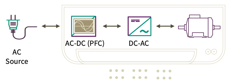
Figure 1: The basic electrical implementation of air conditioning units and heat pumps
With energy prices climbing significantly over the past twelve months, businesses and consumers are starting to feel the pinch. In Europe, gas prices rose by 47% between 2020 and 2021. Countries like Germany rely on gas for a sixth of their electricity generation and, in the US, two-fifths of electricity is generated using natural gas. So, with space and industrial heating consuming around 75% of energy in the EU and cooling demanding 10% of total US electrical energy consumption, the need for more efficient heat pumps and air conditioning solutions is an ever-growing concern.
With many countries banning fossil-fuel-burning equipment, new builds must install electrically powered heating and cooling systems (HVAC). To ensure these are constructed using the best available technology, Europe, North America, and China have defined energy efficiency standards for heat pumps and air conditioners. SEER in North America, and ESEER in the EU, define the (European) Seasonal Energy Efficiency Ratio. This rating defines the ratio of output cooling to input electrical energy (BTU/Watt), adapted to seasonal outdoor temperatures. To get a feel for the rating, upgrading from a SEER 9 to SEER 13 system delivers a power consumption reduction of 30%. A SCOP rating (Seasonal Coefficient of Performance) applies to heating devices.
Basic HVAC Implementation
Whether air conditioning or heat pump, HVAC units have the same basic electrical building blocks. Powered from an AC source, they require an AC-DC power factor correction (PFC) block followed by a DC-AC inverter to power the selected motor (Figure 1). For decades, silicon devices have been the component of choice for such systems, with IGBTs and MOSFETs selected to build the power converter modules. But, with efficiencies regularly sitting above 95% for most power designs, the pathway to higher efficiencies with silicon has become exceptionally short.
Design engineers are increasingly turning to silicon carbide (SiC) alternatives to address this. Such wide bandgap (WBG) technology offers higher efficiency, switching frequency, and design density coupled with overall better performance. The benefits can be attained incrementally by moving to SiC in stages or all in one go by undertaking a bottom-up design approach.
Available Efficiency Improvements with SiC
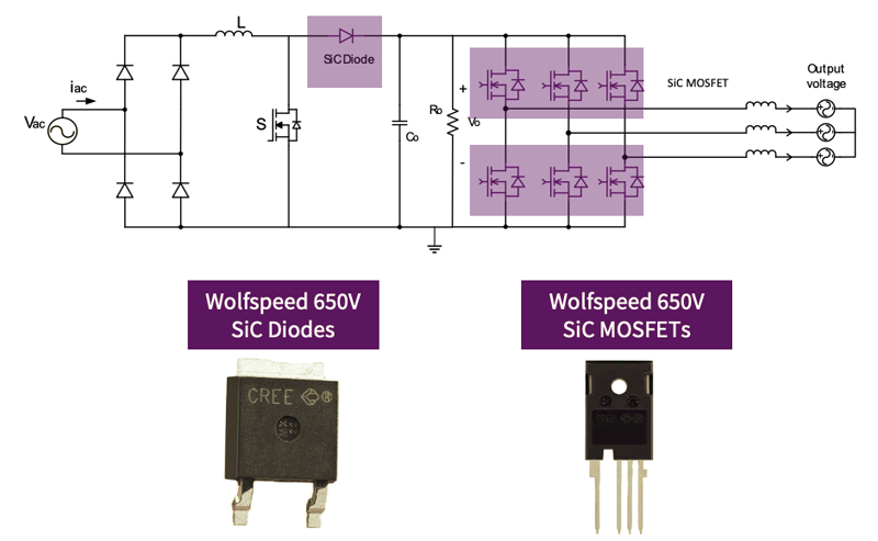
The first change that can be made is in the PFC. In continuous conduction mode (CCM) boost converters, the hard commutated boost diode is typically an ultrafast type. However, this component is a source of power loss due to its reverse recovery properties, particularly as switching frequencies and power densities increase. Moving to a Wolfspeed 650 V C6D series SiC Schottky diode significantly lowers these switching losses (Figure 2). Furthermore, the remaining losses show minimal variation with temperature or current. As a result, a 4kW compressor design driving a motor at 5kHz can attain efficiency gains of around 1.5%, equating to a 60 W reduction in power consumption.
Click image to enlarge
Figure 2: Replacing the fast diode with a SiC alternative provides around a 1.5% improvement in efficiency. Additionally, swapping the IGBTs out for SiC MOSFETs increases this to 3.6%
The next step is to optimize the DC-AC inverter, replacing the silicon IGBTs with appropriate SiC MOSFET alternatives. 650 V C3M series SiC MOSFETs from Wolfspeed offer significant efficiency improvements with lower losses in both turn-on and turn-off characteristics, as well as a lower conduction loss thanks to the improved on-resistance. In the same application, this can deliver around a 2.2% improvement in efficiency, saving 86 W. When combined with the SiC Schottky diode change, the cumulative system efficiency improvement hits 3.6%, reducing losses by 146 W. In terms of SEER rating, this can be equivalent to a ½ SEER improvement.
Click image to enlarge
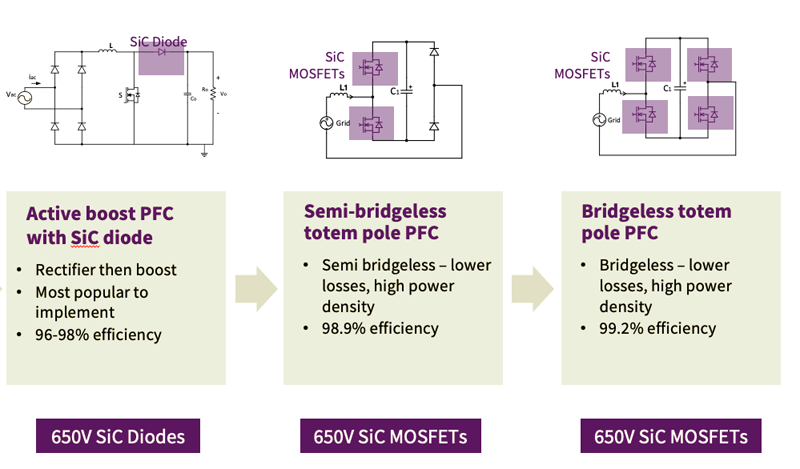
Figure 3: Changing the topology used for the PFC allows the advantages of SiC technology to be fully leveraged
New Power Switches Mean New Topologies
Of course, simply replacing silicon switches with SiC alternatives in an existing design doesn’t realize the full potential of this exciting and new WBG technology. The efficiency of IGBT-based designs drops above a switching frequency of around 5 kHz. In the PFC, new topologies should be considered that use the improvements in SiC characteristics to good effect. One of the most cost-effective PFC topologies is the semi-bridgeless totem pole (Figure 3) . Implemented with just two SiC MOSFETs and a pair of PIN diodes, it offers excellent power density and efficiencies of up to 98.9%. The only concern is a slightly lower light load efficiency compared to full-bridge alternatives.
A bridgeless totem pole PFC requires four SiC MOSFETs but delivers conversion efficiencies of up to 99.2 %. However, this advantage must be weighed up against the increased complexity of the design and the higher overall bill-of-materials (BOM) cost.
Getting Started with SiC
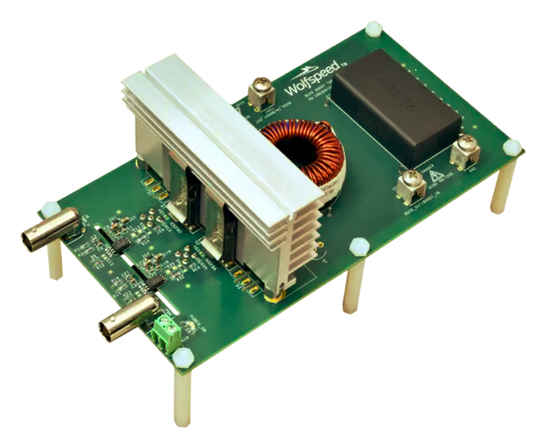
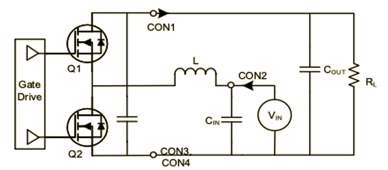
When moving from silicon to SiC, power designers like to take their time getting to know the technology better. With the ability to switch at higher frequencies, the reduced recovery characteristics, and the stability over temperature, it’s essential to operate the switches in a controlled reference application to discover precisely how they operate. To support this, Wolfspeed offers the Buck/Boost Evaluation Board (KIT-CRD-3DD065P) featuring two C3M (C3M0060065K) MOSFETs in TO-247-4 packages and a 300 µH inductor (Figure 4). The board can be operated in either buck or boost mode with input and output voltages of up to 450 VDC and power levels of up to 2.5 kW. It is ideal for measuring timing, overshoot, and switching losses at up to 100 kHz or higher frequencies if an alternative inductor is sourced. Supporting the kit are design files, such as BOM and schematics, and a quick-start video to guide designers.
Click image to enlarge
Figures 4a & 4b: The Buck/Boost Evaluation Board (KIT-CRD-3DD065P) enables power designers to put SiC MOSFETs through their paces
The semi-bridgeless totem pole AC-DC topology (CRD-02AD065N) can be evaluated similarly. Designed for a 180 VAC to 264VAC input, it delivers a 385 VDC output at up to 2.2 kW. This high-efficiency, 80+ Titanium design features the same C3M0060065K discrete SiC MOSFETs with Kelvin connection to overcome the parasitic effects of the package. Operating at 65 kHz, the converter offers a power factor of >.98 and a peak efficiency of 98.5%.
SiC – The Shortest Path to More Efficient HVAC
Wolfspeed, as the inventor of the SiC MOSFET, has been developing the technology for more than thirty years. In that time, SiC has delivered more than seven trillion operating hours in the field. With a firm commitment to WBG, their investments in fabrication facilities will increase capacity by thirty times by 2024. So, with energy prices rising and HVAC manufacturers looking at SiC for their long-term plan to attain higher efficiencies beyond silicon IGBTs and MOSFETs, designers and their purchasing teams can relax.
This is critical because of the market’s concerns over continuously rising energy costs and semiconductor availability. Consumer and commercial buyers are very focused on operating costs, using efficiency labeling in their search for new or replacement heating and cooling units. Switching to SiC can add half a SEER rating to an existing design and, by undertaking a complete redesign that fully leverages the benefits of SiC, the improvements could be even more significant. With a wide range of evaluation platforms available, power designers no longer have any excuse for not taking their first steps with SiC today in order to reap the benefits before the competition does.


