Notable & Newsworthy


.jpg)


Eugenio Schuster, a professor of mechanical engineering and mechanics at Lehigh University's P.C. Rossin College of Engineering and Applied Science, is an expert in nuclear fusion plasma control. He is pictured at Korea Superconducting Tokamak Advanced Research (KSTAR) in South Korea.
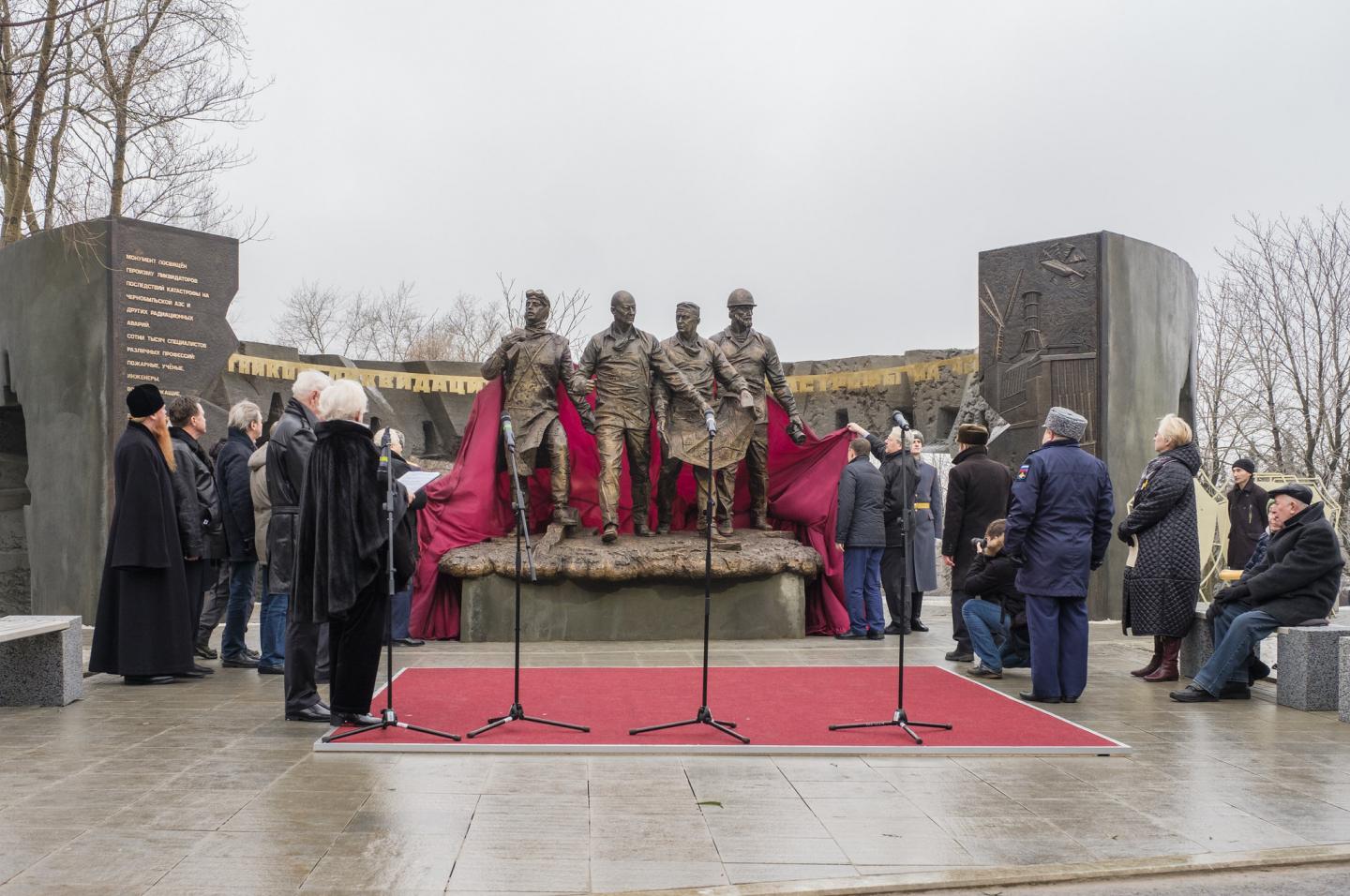
In December 2017, the 'Chernobyl liquidators' monument by Andrei Kovalchuk was ceremonially unveiled on Poklonnaya Hill in Moscow's Victory Park to pay tribute to the people who took part in the clean-up operations after the explosion at the Chernobyl nuclear power plant on April 26, 1986.
Alconbury Weston Limited, a science-engineering company based in the United Kingdom, has licensed carbon fiber technology from Purdue Research Foundation.

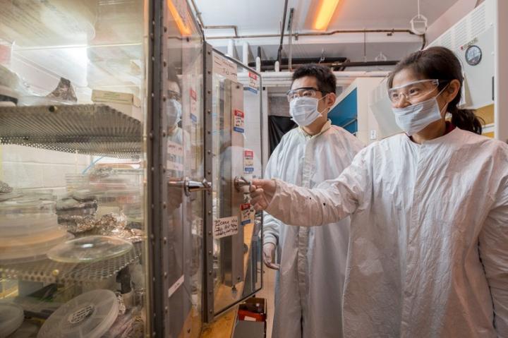
Professor Yuping Zeng (right) and graduate student Peng Cui have worked on designs for transistors that could enable cheaper, faster wireless communications.


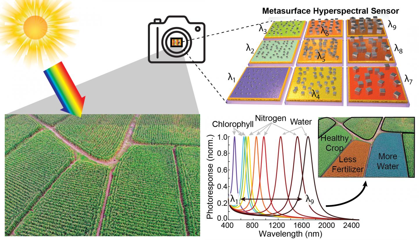
A new type of lightweight, inexpensive hyperspectral camera could enable precision agriculture. This graphic shows how different pixels can be tuned to specific frequencies of light that indicate the various needs of a crop field.
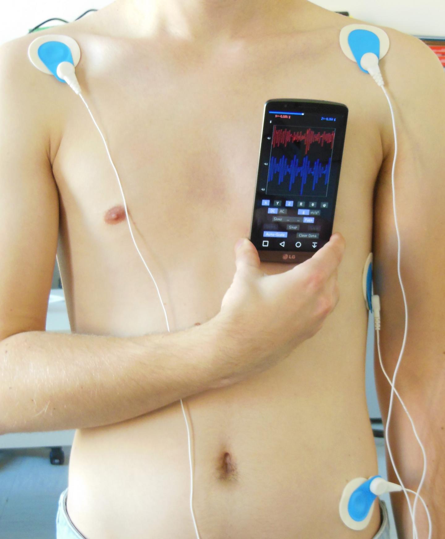
The smartphone used as an instrument readily available, for simple self-monitoring of one's health.

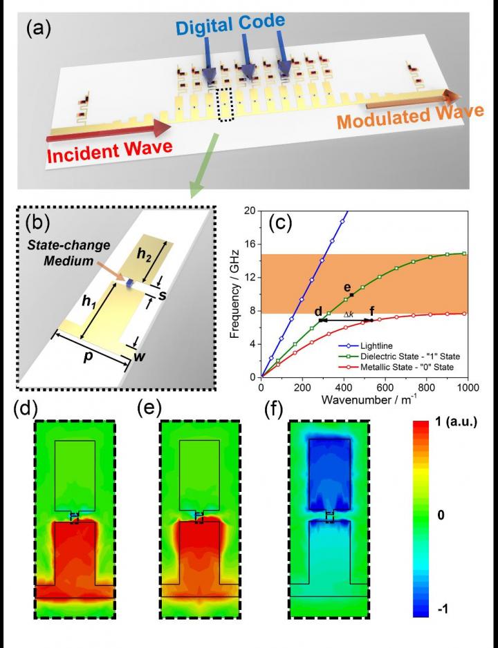
(a) The schematic diagram of the prototype of the digital SSPP waveguide, which is supported by the direct interaction between the incident wave and digital coding. (b) The schematic diagram of a single digital SSPP unit, which is described by the period p = 3.2 mm, strip width w = 0.5 mm, slit width s = 0.45 mm, height of below metallic bar h1 = 3 mm, and height of upper metallic bar h2 = 2.8 mm. (c) The simulated dispersion curves of the digital SSPP unit with different states. (d-f) The Eigen-mode field distributions of the digital SSPP units with '1' state (d & e) and '0' state (f) at 7.2 GHz (d & f) and 10 GHz (e).
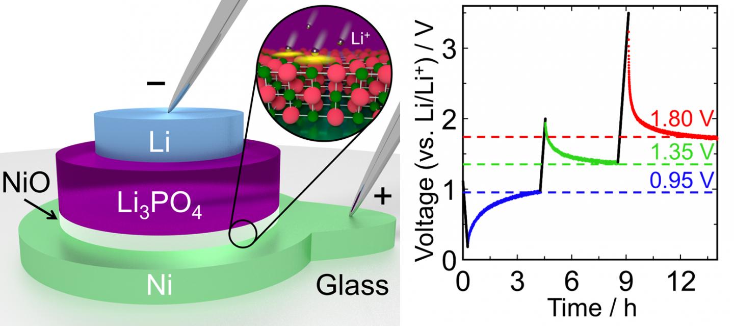
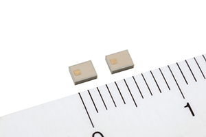
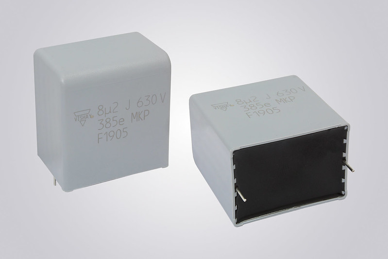
The stacked layers in the proposed memory device form a mini-battery that can be quickly and efficiently switched between three different voltage states (0.95 V, 1.35 V, and 1.80 V).
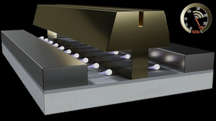
An Army project developed a carbon nanotube technology that, for the first time, achieved speeds exceeding 100GHz in radio frequency applications, and may boost military communications and sensing technologies.
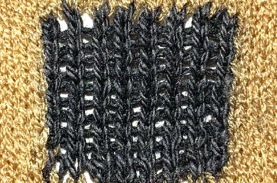
Nanomaterials will be key components for enabling wearable technology, according to an international team of researchers whose comprehensive report on the future of the field was published in science this week.


.png)


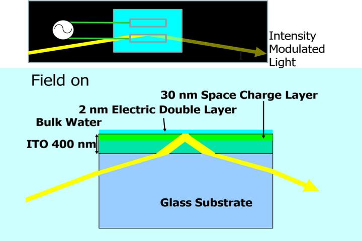
Extracting light modulation using the interfacial Pockels effect.


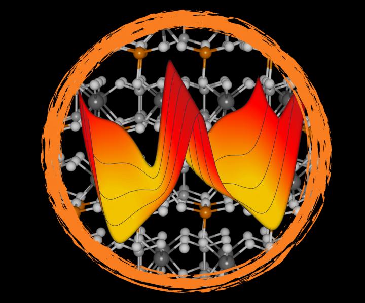
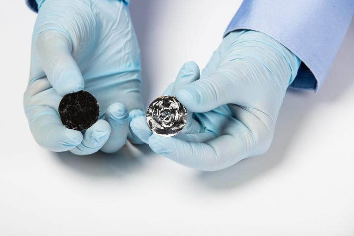
Van-der-Waals layered CuInP2S6 has different properties depending on the locations of copper atoms (orange spheres).

University of Washington researchers have found that air pollution from electricity generation emissions in 2014 led to about 16,000 premature deaths in the continental U.S.


Jason Mical, the Cyber Security Evangelist at Devo


A gallium arsenide wafer cleaved in half using a Sonic Wafering technology developed in the Defect Engineering for Energy Conversion Technologies (DEfECT) Lab at ASU.
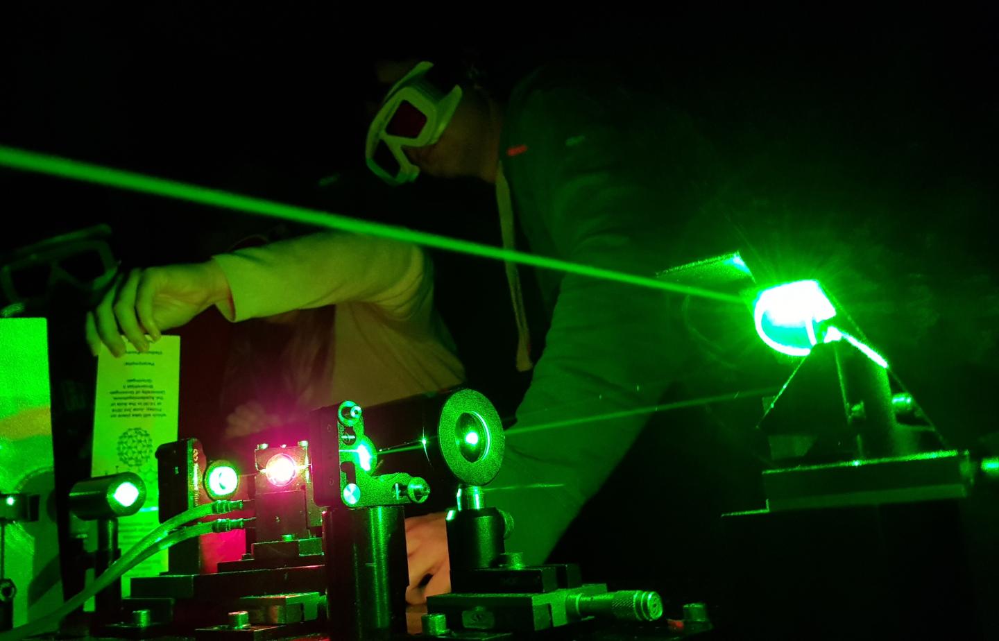
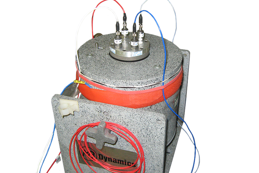
This is a set up for ultrafast spectroscopy, as used in the study.


 - small.jpg)
