Click image to enlarge
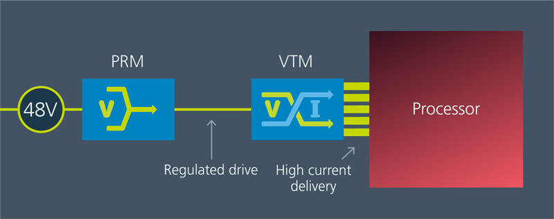
Figure 1: PRM™ and VTM™ are the building blocks of FPA. PRMs are selected based on the system input voltage range and power requirements; VTMs are selected based on the output voltage range and current requirements. The PRM can be mounted anywhere in the system where convenient; the VTM should be mounted as close to the processor core as possible

Click image to enlarge
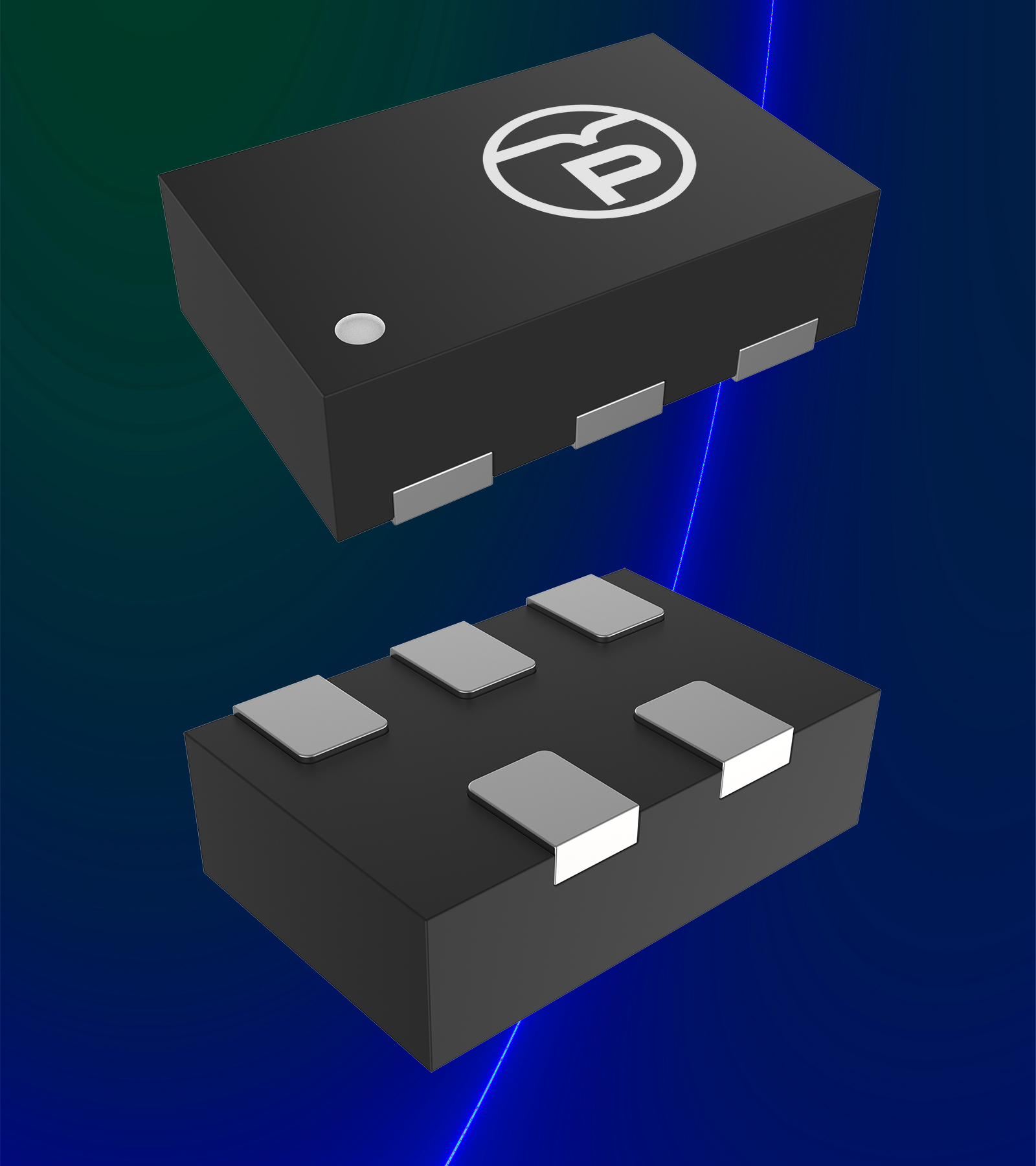
HiperPFS-4 with Integrated 600 V Qspeed Diode Application

Click image to enlarge
BridgeSwitch Application


Edwin Fohtung, an associate professor of materials science and engineering at Rensselaer Polytechnic Institute

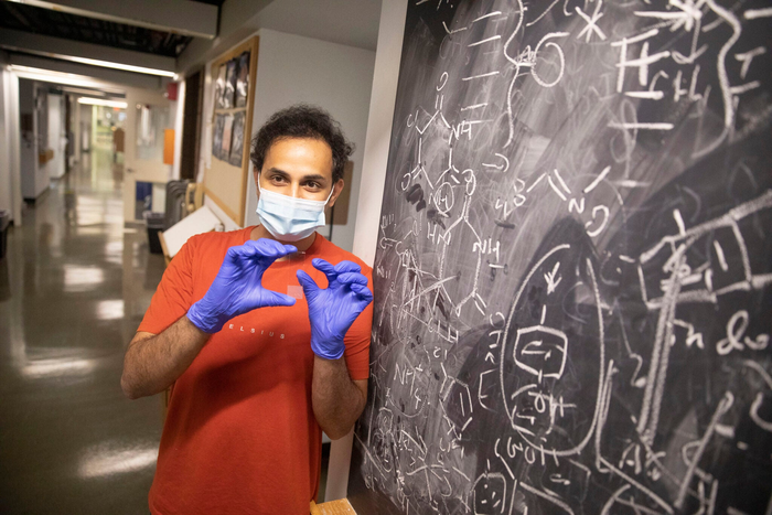
Amit Nagarkar helped develop a data-storage system that uses fluorescent dyes.

Artistic rendering of quarks in deuterium.

KYOCERA AVX’s Ron Demcko


Georgia Papavasiliou, Professor of Biomedical Engineering in Armour College of Engineering at Illinois Institute of Technology (Illinois Tech)

Dean Ian Ferguson with Kennesaw State University

Click image to enlarge
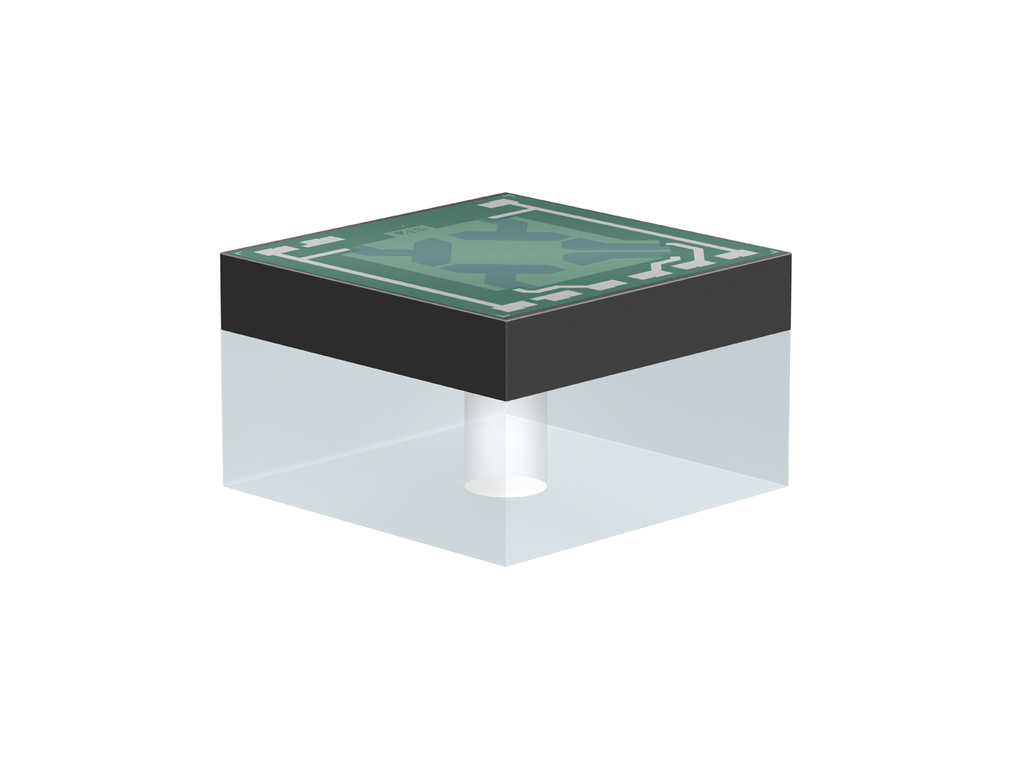
Figure 1: Schematic diagram of a sensor transmission line in an industrial environment
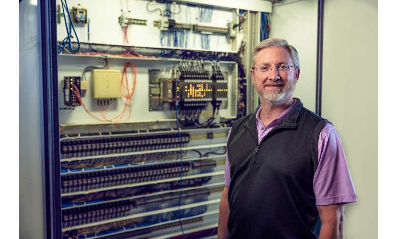
Professor Alan Mantooth from the University of Arkansas
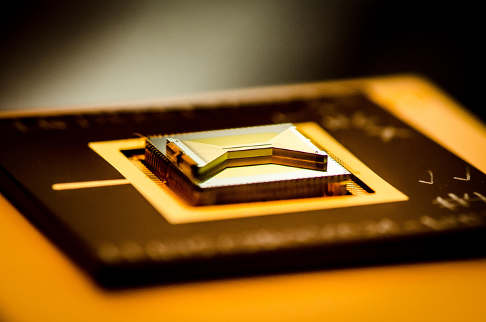
A chip containing an ion trap that researchers use to capture and control atomic ion qubits (quantum bits).
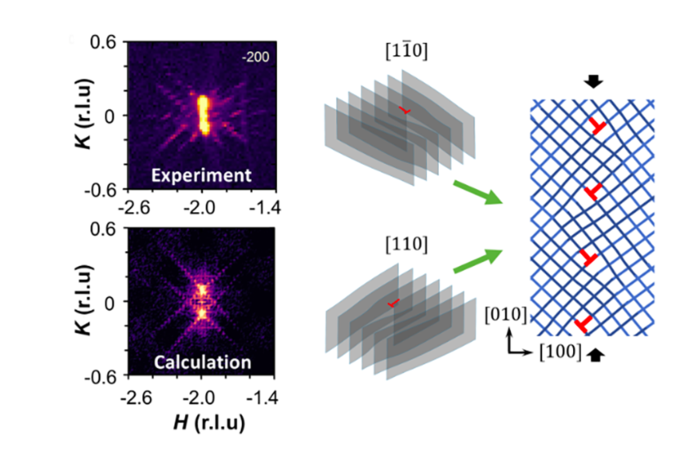
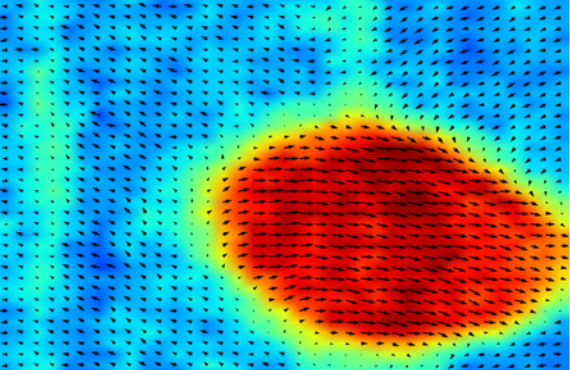
Irreversible, plastic deformation causes extended crystalline defects in the quantum material strontium titanate (SrTiO3) to organize into periodic structures, as revealed by neutron and x-ray scattering processes. These structures enhance electronic properties such as superconductivity.
--10.4.21.png.png)
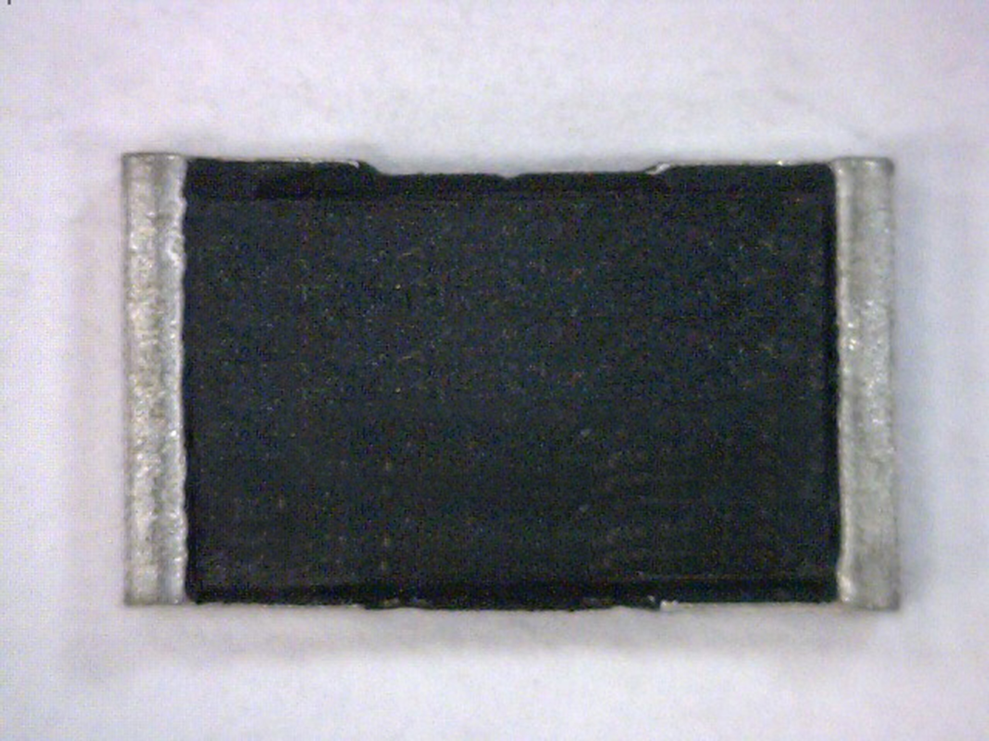
The dark regions in this image show the “dirty white spots” sometimes found in nickel alloy engine components, anomalies that can lead to catastrophic failures. SwRI, under a new FAA contract, will develop new inspection methods to ensure anomalies like these are detected during the manufacturing process.
Click image to enlarge
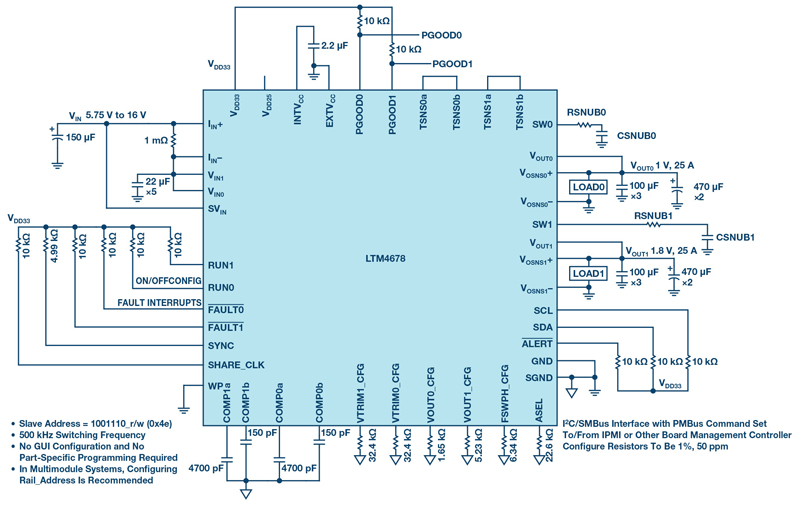
Figure 1. 1V and 1.8 V outputs at 25 A with I2C serial control and monitoring interface.

Click image to enlarge
Figure 1: Measuring heat loss

Click image to enlarge
Figure 1. Haptic use within a car

Click image to enlarge
Figure 1: An example of a standard dc-dc converter application

Click image to enlarge
Figure 1: Industrial Internet of Things is being integrated into many modern manufacturing processes

Click image to enlarge
Figure 1. The skilled manufacturing worker of the future will have IoT expertise in a hybrid environment where employees and robots work together